10
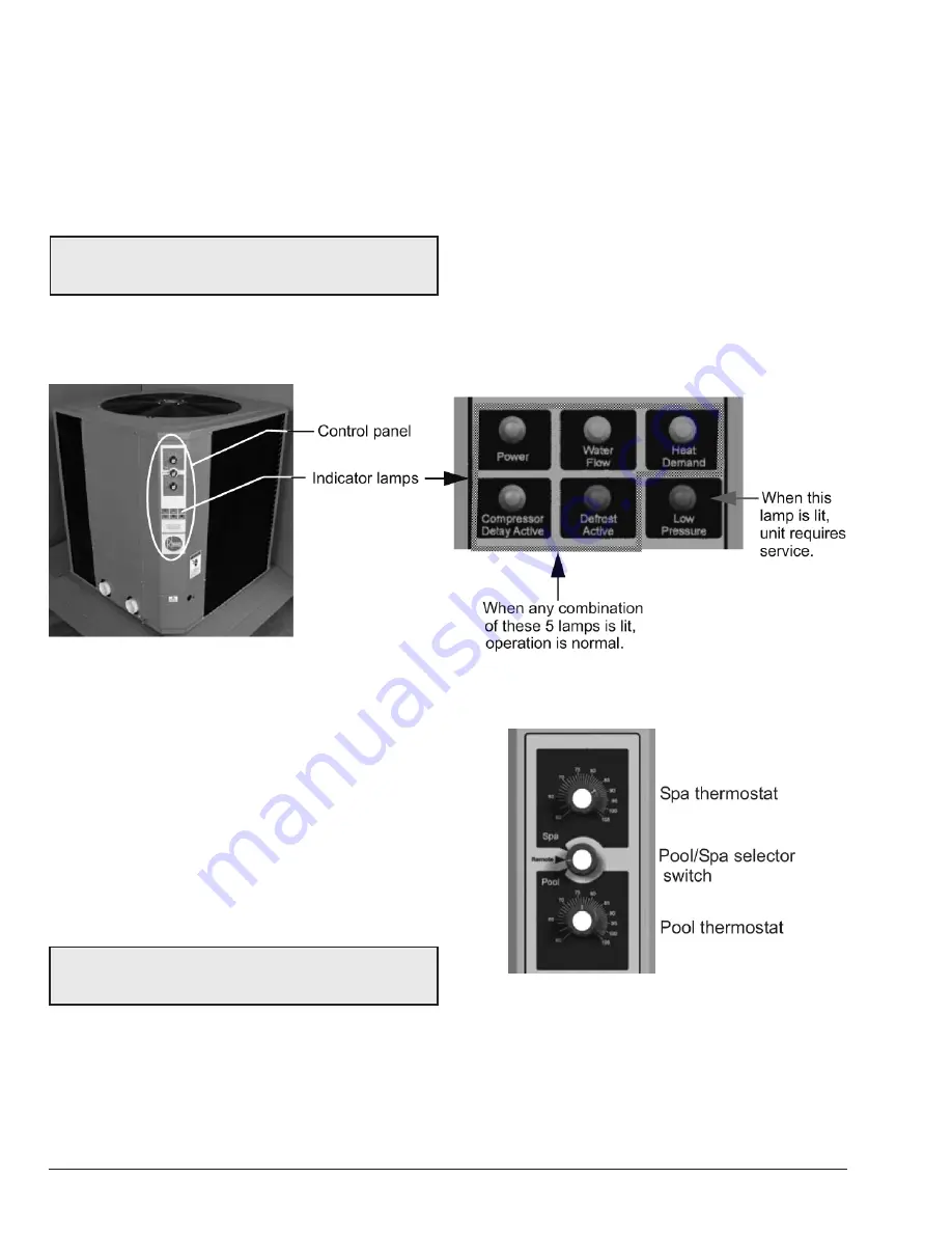
Figure 5. Indicator Lamps — Analog Models
Refrigerant Low Pressure Control
: Stops the compressor
if refrigerant suction (low side) pressure falls too low as
a result of a malfunction, loss of charge or extreme cold
conditions.
Indicator Lamps
: There are 6 indicator lamps located on
the unit control panel (see
Figure 5
):
•
Power (amber lamp)
: When lit, indicates power is
applied to the unit.
NOTE:
The heater will not run when the Remote position
is selected on the Pool/Spa selector switch and there is
no remote control system attached.
•
Water Flow (green lamp
): When lit, indicates normal
water flow.
•
Heat Demand (green lamp)
: When lit, indicates the
actual water temperature is below the target water
temperature.
•
Compressor Delay Active (amber lamp)
: Under
normal operation, when lit, indicates compressor
anti-short cycle timer is active. The fan will run but
the compressor will be OFF for 6 to 8 minutes.
•
Defrost Active (red lamp)
: When lit, indicates unit is
in defrost mode. Defrost mode occurs when ice starts
to form on the outside coil. The fan will continue to
run but the compressor will stay OFF (not heating)
until weather conditions improve.
•
Low Pressure (red lamp)
: When lit, indicates failure
in the refrigeration circuit. When this lamp is ON,
service is required. Call for service assistance.
9. SYSTEM START-UP
1. Verify that the Power lamp is ON and that the pool/
spa pump is running and circulating properly.
2. Verify that the control panel Spa-Remote-Pool switch
is in the Remote (OFF) position; see
Figure 6
.
3. Turn the control switch to either Pool or Spa to turn
the system ON and raise the thermostat setting
above the current water temperature. At this time
the 2 green lamps should illuminate. The fan and
compressor should start up and run simultaneously.
NOTE:
The heater will not run when the Remote position
is selected on the Pool/Spa selector switch and there is
no remote control system attached.
4. Allow the heater to operate for a few minutes to
stabilize operating pressures and to allow various
component temperatures to normalize.
5. Verify that the discharge air temperature is
approximately 8°–10°F (4.4°–5.6°C) cooler than the
air entering the unit. If not, see
"Troubleshooting"
on page 13
.
Figure 6. Selector Knobs — Analog Models
Summary of Contents for 5350 Series
Page 20: ...20 H C F DUAL CAPACITOR V V 208V 230V Single Phase Digital Models 5350 6350 8350 8360...
Page 21: ...21 208V 230V 3 Phase Analog Models 5350 6350 8350...
Page 22: ...22 208V 230V 3 Phase Digital Models 5350 6350 8350...
Page 23: ...23 460V 3 Phase Analog Model 8354...
Page 26: ...26...
Page 28: ...28...
Page 29: ...29...
Page 30: ...30 NOTES Raypak Inc 2151 Eastman Avenue Oxnard CA 93030 805 278 5300 www raypak com...
Page 60: ...30 NOTES Raypak Inc 2151 Eastman Avenue Oxnard CA 93030 805 278 5300 www raypak com...


