INSTALLATION
13
Where the air is sourced DIRECTLY from outside the minimum free area
required for each opening is provided in the table opposite. Where the
ventilation is by an alternate method refer to AS 5601 for ventilation
calculations.
NOTE:
The minimum dimension of any opening shall be 6mm
WARNING!
Air supply to the area where the water heater is installed must
not be affected by mechanical exhaust vents such as kitchen or bathroom
fans, spa blowers, etc. Mechanical exhaust vents may create a negative pressure in the area where the water
heater is installed and can become a hazard by asphyxiation, explosion or fire.
OUTDOOR INSTALLATION
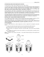
For servicing allow at least 750 mm in front of the water heater for burner
removal and 450 mm on the water connections side for heat exchanger
servicing.
The water heater must NOT be installed inside any roofed structure or under
eaves, roof overhangs, or pool decks.
When installing the water heater on a raised base, the base material MUST be
solid and filled in (e.g. if steel mesh decking is used, a suitable plate material
must be installed to fill in the perforations) to prevent excessive drafts entering
the water heater from underneath.
The following distances extracted from the Australian Gas Installations
Standard AS 5601 must be observed:
At least 500 mm between the top of the flue terminal and the eaves.
At least 1 500 mm horizontally between the flue terminal and the edge of any opening into the building,
measured horizontally.
At least 500 mm between the flue terminal and a return wall or external corner, measured horizontally along the
wall.
At least 1 500 mm below any openable window.
At least 500 mm between the flue terminal and a fence, wall or other obstruction facing the terminal.
HIGH WIND CONDITIONS
In areas where high winds frequently occur, it may be necessary to:
Locate the water heater a minimum of one (1) metre away from high
vertical walls.
Install a wind break to protect the water heater is from the prevailing
winds.
Replace the standard flue terminal with a HIGH WIND top (at extra cost).
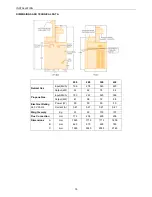
Model
Total area (cm
2
)
200
585
280
825
350
1035
430
1275
Summary of Contents for B0200
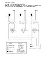
Page 22: ...CONNECTIONS ELECTRICAL 22 WIRING DIAGRAM ON OFF MODELS...
Page 23: ...CONNECTIONS ELECTRICAL 23 WIRING DIAGRAM MODULATING MODELS...
Page 31: ...TEMPERATURE CONTROL 31...
Page 36: ...36 This page is intentionally blank...
Page 37: ...37 This page is intentionally blank...


