background image

ABOUT YOUR WATER HEATER 


SAFETY 

For your safety do not operate this water heater before reading this instruction booklet. 

This water heater is supplied with an electronic thermostat, high limit thermostat and a pressure relief valve. These 
devices  must  not  be  tampered  with  or  removed.  The  water  heater  must  not  be  operated  unless  each  of  these 
devices is fitted and is in working order. 

Improper  installation,  adjustment,  alteration,  service  or  maintenance  can  cause  injury  or  property  damage.  For 
assistance or additional information consult your Raypak distributor, qualified installer, or Rheem

®

 Service agent. 

The  warranty  can  become  void  if  relief  valves  or  other  safety  devices  are  tampered  with  or  if  the 
installation is not in accordance with these instructions. 


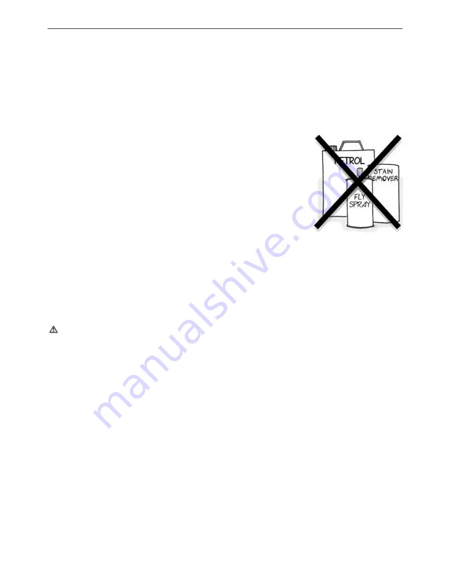
DO  NOT store 

flammable  or  combustible materials

  near  the  water  heater. 

Flammable  liquids  (such  as  petrol),  newspapers  and  similar  articles  must  be 
kept well away from the water heater and the draught diverter or flue terminal. 


DO NOT use 

aerosols, stain removers and household chemicals

 near the 

water  heater  whilst  it  is  working.  Gases  from  some  aerosol  sprays,  stain 
removers  and  household  chemicals  become  corrosive  when  drawn  into  a 
flame. 


DO  NOT  store 

swimming  pool  chemicals,  household  cleaners,

  etc.,  near 

the water heater. 


DO NOT place anything on top of the water heater or in contact with the flue 
terminal. Ensure the flue terminal is not obstructed in any way at any time. 


DO NOT use Propane / Butane gas mixtures in a Propane model. A Propane model is designed to operate on 
Propane  only.  The  use  of  Propane / Butane  mixture,  such  as  automotive  LPG  fuel,  in  a  Propane  model  is 
unsafe and can cause damage to the water heater. 


DO NOT operate with panels, covers or guards removed from the water heater. 


DO NOT enclose this water heater (applies to external installations only). 

Do  not  use  the  water  heater  if  any  part  has  been  under  water.  Immediately  call  Rheem  Service  or  Accredited 
service Agent to arrange for an inspection. 
 

TO TURN ON THE WATER HEATER 

 Warning:

 If you smell gas do not attempt to turn on the water heater. 


Fill the system with water (refer to “

To Fill the Water Heater

” on page 

39

). 


Open the gas isolation valve fully at the inlet to the water heater. 


Switch  on  the  electrical  supply  at  the  water  heaters  isolation  switch. 

NOTE

:  If  the  water  heater  is  correctly 

installed, this will also activate


the circulating pump. 

The water heater will operate automatically when a call for heat occurs. 
 

WHAT TO DO IF YOU SMELL GAS? 


DO NOT try to light any gas appliance. 


DO NOT touch any electrical switch. 


TURN OFF the gas supply at the gas meter immediately, call your gas supplier or licensed gasfitter. 

NOTE:

 Some gases are heavier than air and it may be necessary to check for gas leaks at floor level.  


TO TURN OFF THE WATER HEATER 

If it is necessary to turn off the water heater: 


Switch  off  the  electrical  supply  at  the  water  heaters  isolation  switch. 

NOTE

:  If  the  water  heater  is  correctly 

installed, this will also shut down


the circulating pump. 


Close the gas isolation valve at the inlet to the water heater. 


Close the cold water isolation valve at the inlet to the water heater. 


Close  the  isolation  valves  on  the  cold  and  hot  water  branches  to  shut  down  an  individual  water  heater  in  a 
bank (water heating applications only). 

Summary of Contents for B0507

Page 1: ...2 B0972 NCO NCM PCO PCM B0538 B1182 B1142 B0658 B1292 B1242 B0768 B1412 B1362 B0868 B1722 B1662 B1922 B1852 B2214 B2004 B2634 B2404 B3164 B2804 B3694 B3304 B4224 B3804 This water heater must be installed and serviced by a qualified person Please leave this guide with a responsible officer ...

Page 2: ...nstall this water heater and ask for your Compliance Certificate Warning Upon completion of the installation and commissioning of the water heater leave this guide with the householder or a responsible officer DO NOT leave this guide inside of the cover of the water heater as it may interfere with the safe operation of the water heater or ignite when the water heater is turned on PATENTS This wate...

Page 3: ...ater 4 How Your Water Heater Works 7 Save A Service Call 8 Regular Care 10 Installation 11 Connections Plumbing 15 Connections Electrical 24 Location Of Controls 34 Safety Precautions 35 Commissioning 36 Operating The Water Heater 39 Component Checks Adjustment Procedures 40 Temperature Control 43 Service Procedures 50 Water Supplies 51 Dimensions and Technical Data 52 Warranty 56 ...

Page 4: ...t cause scald injury We recommend and it may be required by regulations that an approved temperature limiting device be fitted into the hot water piping to the bathroom and ensuite when this water heater is installed This will keep the water temperature below 50 C at the bathroom and ensuite The risk of scald injury will be reduced whilst still allowing hotter water to the kitchen and laundry TEMP...

Page 5: ... Propane only The use of Propane Butane mixture such as automotive LPG fuel in a Propane model is unsafe and can cause damage to the water heater DO NOT operate with panels covers or guards removed from the water heater DO NOT enclose this water heater applies to external installations only Do not use the water heater if any part has been under water Immediately call Rheem Service or Accredited se...

Page 6: ...e not limited to the water chemistry the water pressure the water temperature inlet and outlet and the water usage pattern Refer to Precautions on page 6 PRECAUTIONS Where damage to property can occur in the event of the water heater leaking the water heater must be installed in a safe tray Construction installation and draining of a safe tray must comply with AS NZS 3500 4 and all local codes and...

Page 7: ...nd only allows the gas control to open when the burner requires gas for heating The electronic thermostat has a number of parameters that are programmed during manufacture To adjust the parameter settings refer to Temperature Adjustment On Off Models IC902 Electronic Thermostat on page 43 Warning Advice should be sought from your local Raypak representative prior to altering any electronic thermos...

Page 8: ...Hotter water increases the risk of scald injury Water heater size Do you have the correct size water heater for your requirements The sizing guide in the Raypak sales literature and on the Rheem website www rheem com au suggests average sizes that may be needed WATER HEATER NOT OPERATING If the system water temperature is abnormally low the ignition system may have locked out A lockout condition i...

Page 9: ...may indicate the mains water pressure sometimes rises above the designed pressure of the water heater Ask your installing plumber to fit a pressure limiting valve Warning Never replace the pressure relief valve with one of a pressure rating greater than 850 kPa EXPANSION CONTROL VALVE RUNNING If an expansion control valve is fitted in the cold water line to the water heater refer to Cold Water Con...

Page 10: ...e 51 EXPANSION CONTROL VALVE In many areas including South Australia Western Australia and scaling water areas an expansion control valve is fitted to the cold water line to the water heating system The expansion control valve may discharge a small quantity of water from its drain line during the heating period instead of the pressure relief valve on the water heater Operate the easing lever on th...

Page 11: ...pe is marked on the side panel near the gas connection entry and is also shown on the water heaters rating label READ THESE INSTRUCTIONS IN FULL INSPECTION OF EQUIPMENT Check the water heater and associated equipment for any damage DO NOT INSTALL OR OPERATE ANY WATER HEATER THAT HAS BEEN DAMAGED ANY ADDITIONAL DAMAGE OR FAULTS CAUSED BY UNAUTHORISED START UP MAY NOT BE COVERED BY WARRANTY WATER HE...

Page 12: ...nits If the unit is to be installed in front of wall ESV inspectors will require the outer rim of the cowl to be 1 metre from the wall The normal water heater design is with the water pipe entry from the left hand side For servicing purposes allow the required clearance as shown in the table in front of the water heater for burner tray removal INDOOR INSTALLATION The correct draught diverter must ...

Page 13: ...installed to fill in the perforations to prevent excessive drafts entering the water heater from underneath The following distances extracted from the Australian Gas Installations Standard AS NZS 5601 or AS NZS 5601 1 must be observed At least 500 mm between the top of the flue terminal and the eaves At least 1 500 mm horizontally between the flue terminal and the edge of any opening into the buil...

Page 14: ...ng water temperatures are not delivered to a bathroom ensuite or other ablution or public area Where a temperature limiting device is installed adjacent to the hot water storage tanks the cold water line to the temperature limiting device can be branched off the cold water line either before or after the isolation valve pressure limiting valve and non return valve to the storage tanks If an expans...

Page 15: ...let Water R3 80 R3 80 R3 80 R3 80 R3 80 Relief Valve On Off Models RC 20 RC 20 RC1 25 RC1 25 RC1 25 Modulating Models RC1 32 RC1 32 RC1 40 RC1 40 RC1 40 Gas Natural On Off R2 50 R2 65 R2 65 R2 65 R3 80 Natural Modulating R2 50 R2 65 R2 65 R3 80 R3 80 Gas Propane On Off R1 40 R1 40 R1 40 R1 40 R1 40 Propane Modulating R1 40 R1 40 R1 40 R1 40 R1 40 All plumbing work must be carried out by a qualifie...

Page 16: ...3 80 120FB 2 65 80 100 125 125 1852 1922 50 120FB 3 80 120FB 2 65 80 100 125 125 2004 2214 50 120FB 3 80 120FB 3 80 100 125 125 125 2404 2634 80 120FB 2 80 120FB 3 80 100 125 150 150 2804 3164 80 120FB 3 80 120FB 3 80 100 150 150 150 3304 3694 80 120FB 3 80 120FB 4 100 125 150 150 150 3804 4224 80 120FB 3 80 120FB 4 100 125 150 150 150 PUMP SELECTION For the most efficient operation of the water h...

Page 17: ...3 9 95 35 7 47 21 3164 12 62 50 11 47 38 8 6 23 3304 12 62 57 11 79 53 8 84 30 3694 12 62 54 12 62 54 10 03 30 3804 12 62 60 12 62 57 10 09 42 4224 12 62 57 12 62 57 11 47 42 Intermittent Pump Operation Where pump operation is intermittent a remote thermostat must be fitted in the system and a pump run on timer is required to remove residual heat from the water heater and prevent nuisance tripping...

Page 18: ...ks CAUTION Care is necessary when tightening fittings into the gas control or pressure regulator The gas control or pressure regulator casting may crack if the fittings are over tightened Cracked castings are not covered under warranty Damaged gas controls and pressure regulators must be replaced COLD WATER SUPPLY MAKEUP All pipe work must be cleared of foreign matter before connection and purged ...

Page 19: ...om the relief valve In locations where water pipes are prone to freezing the drain line must be insulated and not exceed 300 mm in length In this instance the drain line is to discharge into a tundish through an air gap of between 75 mm and 150 mm The drain lines from each relief valve can discharge into a common tundish This also applies to the drain lines from each water heater in multiple insta...

Page 20: ...meter and length and be fitted with identical ball or gate valves refer to diagram below 2 The heating water manifold heating header assembly must be designed to balance the flow from each unit i e each branch line must be the same diameter and length and be fitted with identical ball or gate valves refer to diagram opposite 3 The hot water manifold hot header assembly must be designed to balance ...

Page 21: ...BING 21 Plumbing Diagrams RAYPAK SINGLE WATER HEATER SINGLE TANK Typical Installation One Water Heater One Storage Tank Typical Installation Two Water Heaters Two Storage Tanks RAYPAK TWO WATER HEATERS TWO TANKS LEGEND ...

Page 22: ...lways be provided at the cold water inlet and hot water outlet on the water heater to allow for disconnection of the water heater Each high point of the system should be fitted with an air bleed valve or automatic air eliminator On radiator or heating systems where thermostatic or zone valves will vary the water flow through the load a by pass with a suitable control valve must be installed to con...

Page 23: ...s the inlet and outlet pipes 3 Select the pipe size between the heater and the system loop main equal to the inlet outlet header connections of the water heater as a minimum 4 Install the correct pump The temperature rise must be between 10 C and 15 C Refer to the Pump Selection and Pipe Size table on page 16 Typical Installation Closed Loop Water Source Heat Pump ...

Page 24: ...ater heater if there are additional control circuits not isolated by this switch This label should direct the service person to the isolation switch for that circuit Do not locate conduits across the doors control panel or the top of the water heater Where a conduit is to be mounted on the water heater cabinet there must be a 10 mm air gap between the conduit and the water heater cabinet to preven...

Page 25: ...es 28 to 33 On Off models may be wired as depicted above with the installation of kit 56076874 supplied separately Where a remote thermostat such as a tankstat is utilised the water heaters electronic thermostat set point should be adjusted to 5º higher than the setting on the remote thermostat Refer to Temperature Control on page 43 POWER FLUEING If the flue cannot be designed as outlined in the ...

Page 26: ...CONNECTIONS ELECTRICAL 26 Wiring Diagram for Typical BMS System Interface ...

Page 27: ...HEATING SYSTEMS NOTE When connecting additional controls any relays timers or other electrical components must be located in an additional enclosure and must NOT be fitted within the water heater For outdoor installations the enclosure MUST be weatherproof ...

Page 28: ...CONNECTIONS ELECTRICAL 28 WIRING DIAGRAMS ON OFF MODELS 1000MJ NG ...

Page 29: ...CONNECTIONS ELECTRICAL 29 ON OFF MODELS 1000MJ LPG ...

Page 30: ...CONNECTIONS ELECTRICAL 30 ON OFF MODELS 1000MJ ...

Page 31: ...CONNECTIONS ELECTRICAL 31 MODULATING MODELS 1000MJ NG DRAWING No 96159611B ...

Page 32: ...CONNECTIONS ELECTRICAL 32 MODULATING MODELS 1000MJ LPG DRAWING No 96159610C ...

Page 33: ...CONNECTIONS ELECTRICAL 33 MODULATING MODELS 1000MJ DRAWING No 96159613B ...

Page 34: ... gas valve and Siemens SKP15 and SKP25 SKP25 003 actuators Modulating Models Modulating type water heaters are fitted with a Siemens VGD series double block gas valve that has Siemens SKP15 and SKP25 SKP25 703 actuators Modulation is done via a Siemens SQS37 modulating motor The RWF55 electronic thermostat controls the modulating motor so that the gas rate modulates to match the required heating l...

Page 35: ...es Wear suitable loose fitting long sleeved clothing or disposable overalls Wear gloves and eye protection Consult Occupational Health and Safety Authorities for any further information AFTER HANDLING Rinse any exposed skin areas with clean water Wash work clothing separately REMOVAL OF USED PRODUCT Follow the precautions as detailed in the section WHEN HANDLING above over exposure to dust formed ...

Page 36: ...ments of AS NZS 5601 or AS NZS 5601 1 and local authority regulations Mechanical ventilation if provided must be interlocked with the water heater as required by AS NZS 5601 or AS NZS 5601 1 7 Ensure the flue complies with the installation requirements of this manual AS NZS 5601 or AS NZS 561 1 and local authority requirement A power flue if provided must be interlocked with the water heater as re...

Page 37: ...ing label refer to Burner Gas Pressure Adjustment on page 40 Make a visual check of the burners The flame should be blue with a well defined pattern A yellow or floating flame indicates restricted air openings or an incorrect burner gas pressure setting Verify that the high limit thermostat is operating and set correctly refer to High Limit Thermostat Adjustment on page 42 For indoor installations...

Page 38: ...r be less than 41 C 4 If the heater inlet temperature remains less than 10 C higher than the system loop return temperature and valve A is fully open leave valve A fully open and throttle valve B until the heater inlet temperature rises to be 10 C higher than the system loop return temperature 5 Main loop and heater temperatures should be checked regularly throughout the season to prevent condensa...

Page 39: ...lation switch NOTE If the water heater is correctly installed this will also activate the circulating pump The water heater will operate automatically when a call for heat occurs TO TURN OFF THE WATER HEATER If it is necessary to turn off the water heater on completion of the installation such as on a building site or where the premises are vacant then Switch off the electrical supply at the water...

Page 40: ...r refit RV20LM adjustment screw cap remove manometer refit pilot solenoid gas test point screw and refit pilot solenoid gas test point cover BURNER GAS PRESSURE ADJUSTMENT On Off Models Natural Gas 507 992 Propane 507 1922 On Off type water heaters models 507 992 natural gas and models 507 1922 propane gas are fitted with a Brahma GVC30 double block gas valve and a Jeavons J48 appliance regulator ...

Page 41: ...3kPa propane models by turning the outer regulator screw on the SKP25 actuator clockwise to increase pressure or anticlockwise to decrease pressure refer to Diagram B High Gas Rate Adjustment 6 Press and hold ESC on the RWF55 electronic thermostat for 5 seconds to enter manual mode HAnd appears on the lower display the current water temperature is shown on the upper display 7 Refit the SQS37 modul...

Page 42: ...h limit front cover 2 Using a small flat bladed screwdriver rotate the adjustment dial so that the dial pointer aligns with the required temperature setting 3 Refit high limit front cover and restore power To reset the high limit To reset the high limit refer to High Limit Thermostat on page 34 KOL RUN ON TIMER ADJUSTMENT The following procedure details the method of setting the optional run on ti...

Page 43: ...thermostat which has the following features The thermostat display shows the current tank sensor temperature during normal operation The thermostat has parameters that control system operation Refer to IC902 Parameters on page 43 Thermostat set point parameters parameter options and parameter settings or parameter information can be viewed or adjusted Refer to IC902 Adjustment Procedures on page 4...

Page 44: ...ters to copy card N A N A N A N A 1 Set point may differ to setting shown in Raypak Setting column Note If a level 1 parameter shown with an asterisk is modified the thermostat must be reset to ensure correct operation To reset the thermostat remove the power supply to thermostat wait ten seconds and then restore the power supply IC902 Adjustment Procedures Notes to all IC902 thermostat adjustment...

Page 45: ... The thermostat can be locked to prevent any changes to system status parameters only set point SEt and tank sensor offset calibration CA1 System status parameters can still be viewed and level 1 parameters can be accessed and changed The thermostat can be locked to prevent access to level 1 parameters only System status parameters set point SEt and tank sensor offset calibration CA1 can still be ...

Page 46: ... conditions including a power outage parameter settings do not require adjustment however parameter settings may be altered to fine tune a system to suit a particular installation The parameter menu is comprised of a process data level parameter menu a parameter level parameter menu and a configuration level parameter menu The following tables detail all available parameters each parameter range a...

Page 47: ... normal whilst performing any thermostat adjustment procedure Checking or Adjusting RWF55 Set Point 1 Press and release the button the current set point temp green display will start flashing 2 Press and release or to adjust the set point to the required value 3 Press and release ENTER to confirm the new setting The green display will stop flashing and the new set point will be displayed Checking ...

Page 48: ...ther than that given in the tables To select a menu 1 Press ENTER OPr appears in the lower display 2 Press and release the down button twice ConF appears in the lower display 3 Press and release ENTER InP is shown on the display 4 Press and release the down button to scroll through the various menus InP Cntr rAFC AF OutP binF diSP IntF To select a sub menu and adjust parameters 5 Once the required...

Page 49: ...nstant is used to adapt the digital 2nd order input filter time in s 0 s filter off If the input signal changes abruptly approx 26 of the change is captured after a time corresponding to the filter time constant dF3 2 x dF3 approx 59 is captured 5 x dF3 approx 96 is captured The following parameters determine the target temperature for a particular outdoor temperature and also set the heating curv...

Page 50: ...s flame is not normal and can cause sooting under prolonged operation 12 Clean and remove any dust and debris from the water heater and its immediate area 13 Refit burner access door s and header access panels ANNUAL SERVICE PROCEDURE 1 Conduct the Six Monthly Service Procedure detailed above PLUS 2 Isolate gas electricity and water supplies 3 Disconnect and remove the burner tray 4 Check igniter ...

Page 51: ...er heater and the temperature pressure relief valve and cylinder of the storage tank connected to the system Refer to the Cold Water Connection Plumbing Diagram on page 15 for the position of the expansion control valve Where the saturation index exceeds 0 80 the Rheem warranty does not apply to a copper heat exchanger in a Raypak water heater Water which is scaling may be treated with a water sof...

Page 52: ...kW 115 120 150 170 195 Propane Gas Input MJ h 485 505 620 720 820 Output kW 108 115 140 160 180 Electrical Rating 240 V 50 Hz Power W 50 50 50 50 50 Current A 0 21 0 21 0 21 0 21 0 21 Weight empty Kg 115 195 200 250 260 Flue Connection mm 255 255 305 305 355 Dimensions A mm 1085 B mm 835 830 955 1055 1160 C mm 2145 2130 2255 2255 2355 ...

Page 53: ...ht empty Kg 310 330 360 390 440 460 Flue Connection mm 355 405 405 455 455 505 Dimensions A mm 1810 1915 1915 1990 2060 2130 B mm 1330 1510 1615 1740 2070 2270 G mm 860 860 860 860 930 930 Model 2214 2634 3164 3694 4224 Natural Gas Input MJ h 2215 2636 3165 3692 4224 Output kW 505 600 720 840 960 Propane Gas Input MJ h 2150 2530 3035 3540 4045 Output kW 480 560 675 790 900 Electrical Rating 240 V ...

Page 54: ...42 0 42 0 42 0 42 0 42 0 42 Weight empty Kg 360 385 410 440 510 520 Dimensions A mm 2500 2395 2395 2570 2640 2920 B mm 1330 1510 1615 1740 2070 2270 Model 2004 2404 2804 3304 3804 Natural Gas Input MJ h 2004 2404 2804 3304 3804 Output kW 445 530 625 740 845 Propane Gas Input MJ h 1595 2530 2278 2659 3038 Output kW 354 560 508 595 675 Electrical Rating 240 V 50 Hz Power W 100 100 100 100 100 Curren...

Page 55: ...55 This page is intentionally blank ...

Page 56: ... s office and the installed site shall be the owner s responsibility 2 5 Where the water heater is installed in a position that does not allow safe or ready access the cost of that access including the cost of additional materials handling and or safety equipment shall be the owner s responsibility In other words the cost of dismantling or removing cupboards doors or walls and the cost of any spec...

Page 57: ... wish to make a claim under this warranty you need to a Contact Rheem on 131031 and provide owner s details address of the water heater a contact number and date of installation of the water heater or if that s unavailable the date of manufacture and serial number from the rating label on the water heater b Rheem will arrange for the water heater to be tested and assessed on site c If Rheem determ...

Reviews: