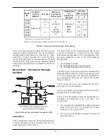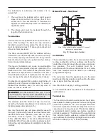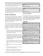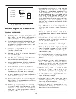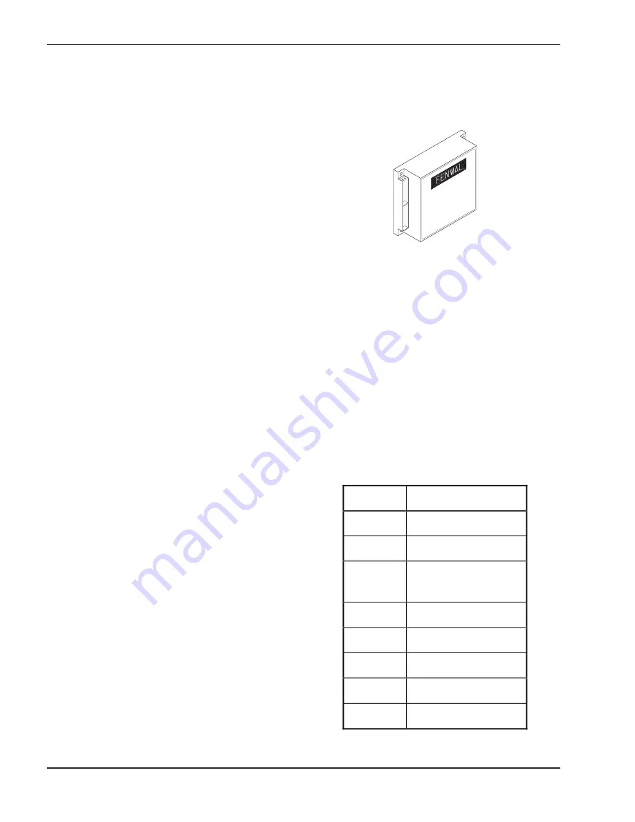
Ignition Module
When additional heat is needed, the combustion air
blower starts to purge air from the combustion cham-
ber for about 15 seconds. On proof-of-air flow, the
air-proving switch closes and the igniter is energized.
To ensure safe operation, the gas valve cannot open
until the igniter is verified. The main burner is automat-
ically lit when the device is powered and pre-purged.
The heater performs its own safety check and opens
the main valve only after the igniter is proven to be
capable of ignition.
The standard ignition module will attempt to light three
times before locking out. To reset it, turn off power to
the heater, wait 30 seconds and re-apply power. The
optional single-try ignition module will lock out after
failing to light one time. To reset it, press and release
the small, recessed black push button located inside of
the cut-out on the lower right-hand corner of the igni-
tion module case. Turning off the power to the heater
WILL NOT reset the ignition module.
Code
Condition
On
System OK;
No faults present
Off
Possible control fault;
Check power
1 Flash
Low air pressure, brief flash-
ing normal on start-up
2 Flashes
Flame in combustion
chamber; No call for heat
3 Flashes
Ignition lockout
4 Flashes
Low igniter current
5 Flashes
Low 24VAC, check control
supply voltage
6 Flashes
Internal fault;
Replace control
Fig. 29: Ignition Module
Table Q: Ignition Module
Diagnostic LED Codes
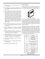
36
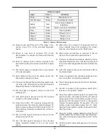
45. The stage 1 LED on the status display board is
now illuminated.
46. The coil of relay K-2 is now energized with the
N.O. contacts closing downstream of the stage 2
connections.
47. The gas coming through the burners should ignite
from the heat of the hot surface igniter and the
flame should carry over from one burner to the
other burners of stage 1. The remote sensor is
now trying to sense the flame. If the flame is not
sensed within 4 seconds, the ignition module will
shut down gas valve 1 and retry the hot surface
igniter. During ignition retry the heater must per-
form a 15-second pre-purge and an approximately
30-second igniter warm-up before opening gas
valve 1 again. The standard ignition module will
attempt ignition a maximum of three times prior to
ignition lockout.
48. If the ignition module locks out, a signal will be
sent to the Universal Diagnostics Board to indicate
an ignition fault.
49. (Models 302B-402B only) 24 VAC is now waiting
at pin 3 of the stage 2 connections on the CPW
board.
50. (Models 502B-902B only) When power is sent to
gas valve 1 it is also sent to time delay relay 1 (TD-
1) which starts a 5-second countdown.
51. (Models 502B-902B only) After the 5-second
countdown from TD-1, 24 VAC is waiting at pin 3
of the stage 2 connections on the CPW board.
52. After closure of the stage 2 contacts Gas valve 2
is energized.
53. The stage 2 LED on the status display board is
now illuminated.
54. The Heater is now operating at full fire.
Summary of Contents for HI DELTA 302B
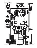
Page 45: ...45 Wiring Diagram...
Page 59: ...59...

