16
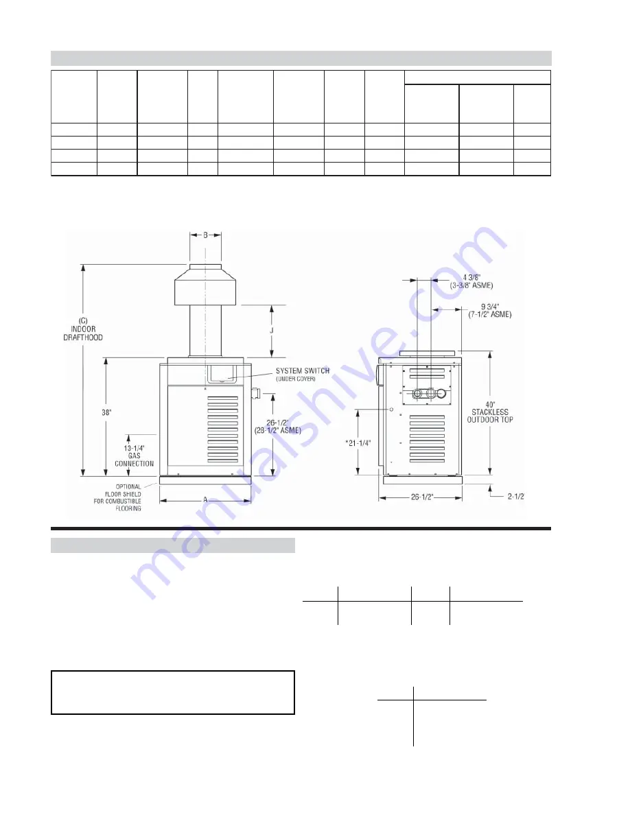
SPECIFICATIONS AND DIMENSIONS
*Electrical Connection On Left Side is 19-1/8".
a. All Air From Inside The Building:
Each opening shall have a minimum net free square
inches as noted:
Model Square Inches Model Square Inches
185
181
335
333
265
264
405
399
b. All Air From Outdoors:
When air is supplied directly from outside of building,
each opening shall have a minimum net free square
inches as noted:
Model Square Inches
185
46
265
66
335
84
405
100
COMBUSTION AIR (Indoor Units Only)
Air For Combustion And Ventilation
The heater must have both combustion and ventilation air.
Minimum requirements for net free air supply openings,
one 12 inches from ceiling for ventilation and one 12
inches from the floor for combustion air as outlined in the
latest edition of the National Fuel Gas Code, ANSI
Z2231(Canada-CAN/CGA-B149.1 and B149.2) and any
local codes that may have jurisdiction.
*Designation for Propane is "EP", Natural gas is "EN". Prefix "C" is for Cast Iron (ASME) Headers; "P" is for Plastic (Polymer)
Headers. Atmospheric heaters: reduce input 4% for each 1000 ft. above sea level when installed above 2000 ft. elevation.
Low NOx heaters: for elevations above 5,000 feet consult factory.
For Canada
, no de-rate is required for elevations up to
4500 feet. Manufactured under Patent No. 3,623,458.
Note:
Plastic (Polymer) Headers cannot be used for ASME
installations.
Fig # 9037.2
r
e
t
a
e
H
l
e
d
o
M
H
U
T
B
t
u
p
n
I
)
0
0
0
(
)
A
(
t
e
n
i
b
a
C
h
t
d
i
W
)
B
(
e
u
l
F
.
a
i
D
)
C
(
r
o
o
d
n
I
d
o
o
h
t
f
a
r
D
)
J
(
s
a
G
.
n
n
o
C
r
e
t
a
W
.
n
n
o
C
)
s
b
l
(
s
t
h
g
i
e
W
g
n
i
p
p
i
h
S
n
o
r
I
t
s
a
C
r
e
t
a
e
H
s
s
e
l
k
c
a
t
S
/
w
p
o
T
n
o
r
p
a
C
r
e
t
a
e
H
s
s
e
l
k
c
a
t
S
/
w
p
o
T
I
r
o
o
d
n
-
t
f
a
r
D
d
o
o
h
B
5
8
1
R
1
8
1
"
4
/
1
-
8
1
"
6
"
8
/
5
-
2
6
"
6
1
/
1
-
2
1
"
4
/
3
"
2
1
9
1
2
7
1
2
1
B
5
6
2
R
4
6
2
"
8
/
3
-
2
2
"
7
"
8
/
7
-
2
6
"
8
/
1
-
1
1
"
4
/
3
"
2
4
1
2
5
9
1
5
1
B
5
3
3
R
4
3
3
"
4
/
3
-
5
2
"
8
"
4
/
3
-
3
6
"
4
/
3
-
0
1
"
4
/
3
"
2
4
3
2
5
1
2
7
1
B
5
0
4
R
9
9
3
"
4
/
1
-
9
2
"
9
"
8
/
3
-
5
6
"
2
/
1
-
2
1
"
4
/
3
"
2
3
5
2
4
3
2
0
2
CAUTION:
Combustion air must not be contaminated
by corrosive chemical fumes which can damage the
heater and void the warranty.
Summary of Contents for P-R185B To P-R405B, C-R185B To
Page 2: ......
Page 22: ...22 HEATEXCHANGERPRESSUREDROPTABLES ...
Page 26: ...26 WIRING DIAGRAM MILLIVOLT UNITS MECHANICAL THERMOSTAT ...
Page 27: ...WIRING DIAGRAM IID UNITS atmospheric 27 ...
Page 28: ...WIRING DIAGRAM IID UNITS Low NOx 28 ...
Page 42: ...42 DIGITAL CONTROL LOGIC FLOW CHART ...
Page 44: ...44 ...
Page 46: ...46 ...
Page 47: ...47 ...
Page 48: ...48 ...
Page 49: ......
Page 50: ......
Page 51: ...51 ...


