Pin#
Wire Color
Description
L1
Black
Hot 1
L2
Red or White
Hot 2
GRD
Green
Ground
10
WARNING:
All electrical wiring must conform to the local NEC guidelines. A licensed, qualified
electrician should complete the wiring for this product.
Electrical Specifications
1. Voltage: 208-230 VAC, 60 Hz, Single Phase
2. Max Amps: 11
3. Speed Range: 600 - 3450
4. Controller: 208-230 Vrms, Single Phase
5. Ambient: 50
o
C
6. NEMA Type 3R
Table 1.0
Electrical Installation
The motor is designed to handle either a bare wire connection or a quick disconnect connection. The
quick disconnect tab is 0.250”. For a direct wire connection, the wire insulation should be stripped to a
length of approximately 0.33” and the screw tightened to a torque of 10 in-lb. The terminals will handle
wire up to 12 AWG in size.
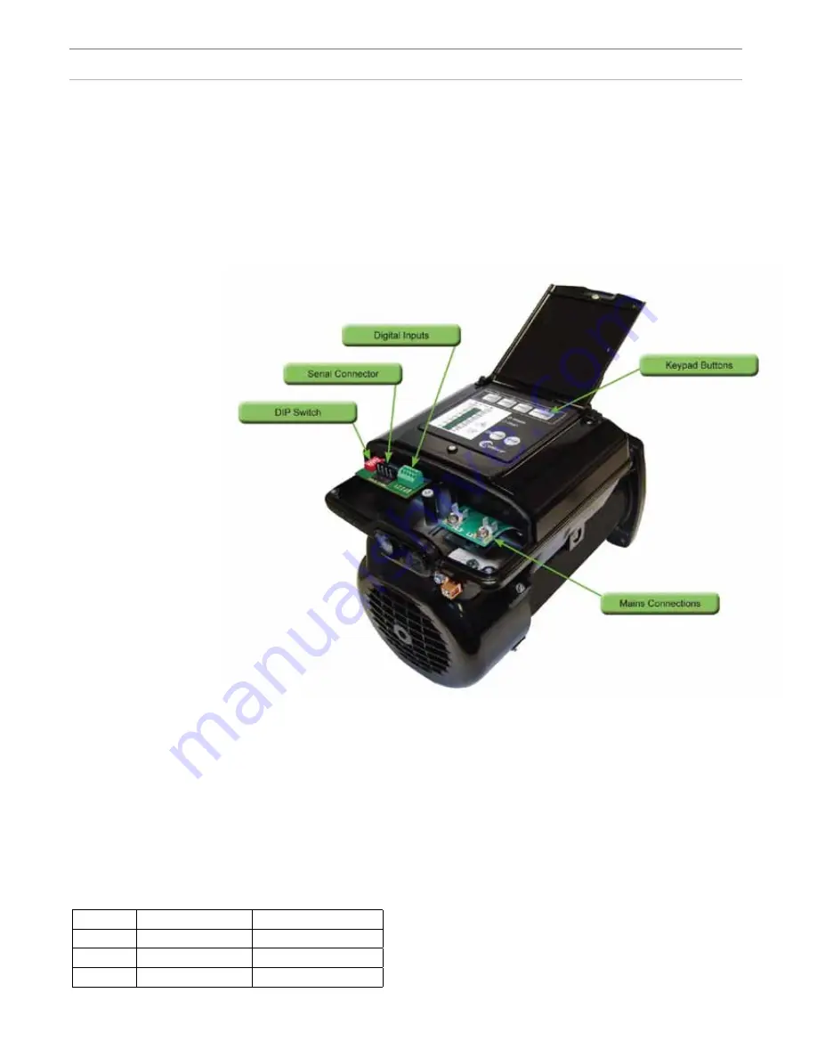
There are two terminals labeled L1 and L2. (See Figure 3) Attach the power leads to these terminals.
Attach the black lead to L1 and the red or white lead to L2. (See Table 1.0) The top rear of the controller
has a single screw. Loosen this screw and lift cover to expose the terminal area.
Figure 2


