7
INSTALLING THE
CONTROL
The control should be mounted on a wall, preferably at
eye level with AC power as close as possible.
Consider the length of cable required for routing along
walls, along pipes, and for connecting the temperature
sensors.
Notice on the bottom of the control that two of the five
knockouts have been removed for routing of cables. If
you want to use one or more of the other knockouts,
these should be removed before mounting the control
onto the wall.
Attaching the Temperature
Sensors
To get an accurate reading of the water temperatures,
the sensors must be in good thermal contact with the
pipe. Follow this procedure when connecting the tem-
perature sensors.
Procedure for Connecting Temperature Sensors to
Pipes:
1. Remove any existing insulation.
2. Clean the pipe surface using sandpaper.
3. Apply thermal conducting paste to the pipe sur-
face.
4. Fasten the sensor tightly to the pipe using the
black cable tie.
5. Attach 18 AWG shielded cable to the 6 in. leads
using wire nuts or electrical tape.
6. Fasten the cable to the pipe using a second black
cable tie.
7. Replace the existing insulation or wrap thermal
insulation tape around the pipe.
Overlap each
turn and DO NOT STRETCH the tape.
On the sensor end, roll the shielding and tape so it will
not contact a conductor. On the control end, the shield
should be grounded.
Do not ground both ends of
the shielding.
Avoid routing wiring on or near other electrical wires,
conduit, motors, spark igniters or other sources of
high, intermittent voltage or current. EMI (spikes) can
disrupt information flow and retention.
Procedure for Installing Supply Sensor in Tank:
1. Install sensor into dry well utilizing thermal con-
ductive paste.
2. Install dry well into tank stat opening.
Providing 24 VAC Power to the
Control
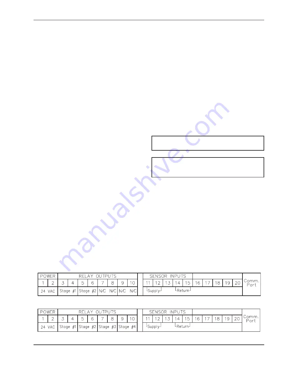
The RayTemp requires an external power transformer
connected at terminals one and two. Complete and
check all wiring before connecting this transformer.
The transformer must be rated for 24 VAC at 16 VA or
higher.
When 24 VAC power is applied to the control the LCD
display will be blank for a few seconds. During this
time the RayTemp is configuring any modem that may
be connected. Afterwards, the opening screen
appears, which identifies the model number, type of
control, software version, and copyright notice.
CAUTION:
DO NOT connect power until all wiring
is complete and checked.
CAUTION:
DO NOT connect 120 VAC to the
RayTemp!!! Resulting damage will void your
warranty.
Fig. 3: Stages and Sensor Connections
2-Stage Control
4-Stage Control


