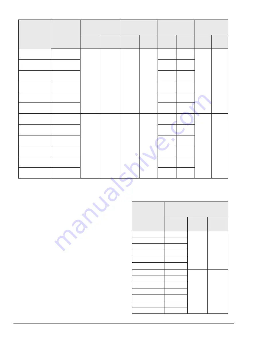
background image

6

Model

X-1 Kit No.

Item 1*

Leg Assembly

Item 3*

Leg Assembly

Item 2*

Support Beams

Item 6*

Cross Members

P/N

Length

(in.)

P/N

Length

(in.)

P/N

Length

(in.)

P/N

Length

(in.)

302

006906

074521

37.75

074520

37.75

402161

42.79

401680 29.8

399-402

006907

402162

49.79

499-502

006908

402163

56.79

649-652

006909

402164

67.29

749-752

006910

402165

74.29

899-902

006911

402166

84.79

989-992

011563

074396

45.95

074395

45.95

402145

64.12

402097 38.0

1259-1262

011564

402146

75.44

1529-1532

011565

402147

86.78

1799-1802

011566

402148

98.12

2069-2072

011567

402149 109.47

2339-2342

011568

402150 120.81

*Item numbers correspond to the numbers listed in Figure 1 on page 5.

Table B. 

PARTS LENGTHS FOR SURERACK ASSEMBLIES

Anchoring Information

For reference only. Recommended to match drill on job 

site.

Use  a  minimum  of  two  bolts  ½”  X  5”, A-307  Grade  5.2 

or  equivalent.  Use  Hilti®  HY-150  adhesive  to  secure 

expansion anchor.
Approved for all installations.
Refer to Figure 2 and Table C for more information.

Model

Anchoring Dimensions (in.)

A

B

C

302

34.29

22.71

3.5

399-402

41.29

499-502

48.29

649-652

58.79

749-752

65.79

899-902

76.29

989-992

55.62

30.81

3.5

1259-1262

66.94

1529-1532

78.28

1799-1802

89.62

1999-2002

100.97

2069-2072

100.97

2339-2342

112.31

Table C. 

ANCHORING DIMENSIONS

Summary of Contents for SureRack Kit

Page 1: ...06 30 22 Replaces 12 09 10 P N 240792 Rev 4 INSTALLATION INSTRUCTION MANUAL SureRack Kit X 3 Restraint Kit FOR HI DELTA MODELS 302 2342 302A 2342A 302B 2342B 302C 2342C AND DELTA LTD MODELS 399 2339 3...

Page 2: ...o coversheet and X 3 Restraint Bracket Kit Added note The SureRack is designed to connect to the lower unit to provide lateral bracing Raypak cannot support using a SureRack as a platform to elevate a...

Page 3: ...3 TABLE OF CONTENTS 1 X 1 KIT CONTENTS 4 Anchoring Information 4 2 INSTALLATION 7 3 X 2 ADD ON LEG KIT 9 4 X 3 RESTRAINT BRACKET KIT 10...

Page 4: ...using a SureRack as a platform to elevate an upper unit with no lower unit 1 X 1 KIT CONTENTS Item Description Qty P N for Sizes 302 902 399 899 P N for Sizes 992 2342 989 2339 Location 1 Leg assembly...

Page 5: ...5 Figure 1 SURERACK ASSEMBLY...

Page 6: ...72 011567 402149 109 47 2339 2342 011568 402150 120 81 Item numbers correspond to the numbers listed in Figure 1 on page 5 Table B PARTS LENGTHS FOR SURERACK ASSEMBLIES Anchoring Information For refer...

Page 7: ...engths for the unit to be installed Refer to Table B 2 Once the unit is located in its permanent position remove the left and right access panels from the front and rear of the boiler as shown in Figu...

Page 8: ...bottom and midsection of the other three legs See Figure 7 16 total 14 Tighten all the leg bolts after all the attaching bolts are in place 15 If it is required that the legs be bolted to the floor fo...

Page 9: ...25 Fully tighten all the nuts and bolts on the restraint feet on the support beams and on the cross members Also re tighten the bolts on the bottom of the rack assembly Figure 11 COMPLETED ASSEMBLY X...

Page 10: ...NC x 2 0 8 550267 ASSEMBLY 1 Place one foot at each corner of the boiler 2 Place one L shaped mounting bracket under the boiler at each corner as shown in Figure 13 3 Insert one 2 bolt and washer thro...

Page 11: ...THE 3 8 16 X 2 SCREW AT THIS LOCATION ONLY ONE ON EACH CORNER OF THE BOILER FLAT SIDE OF RESTRAINT FOOT FACES FORWARD Figure 13 X 3 RESTRAINT FOOT DETAILS Refer to Table C and Figure 2 in this instru...

Page 12: ...12 NOTES Raypak Inc 2151 Eastman Avenue Oxnard CA 93030 805 278 5300 www raypak com...

Reviews: