7
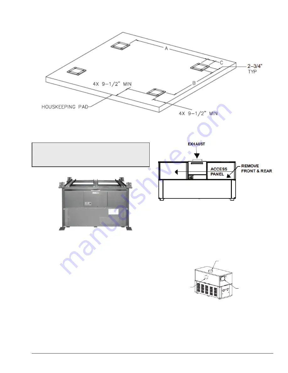
Figure 2.
SURERACK ANCHORING INFORMATION
NOTE:
The rack is to be assembled around the bottom
boiler first. Do not pre-assemble. It is recommended
that the rack be installed first prior to any plumbing,
electrical, venting, or gas hook-up.
Figure 3.
ASSEMBLE RACK AROUND BOTTOM
BOILER
INSTALLATION
READ COMPLETELY BEFORE ASSEMBLING RACK.
1. Identify the heater model number. This information
is on the rating plate located on the lower right front
panel. Confirm correct item lengths for the unit to be
installed. Refer to Table B.
2. Once the unit is located in its permanent position,
remove the left and right access panels from the front
and rear of the boiler as shown in Figure 4.
Figure 4.
FRONT VIEW
3. Reverse the exhaust vent panels to the alternate
locations at rear of the heater on the bottom unit. See
Figure 5. Refer to the heater I&O manual for detailed
instructions (P/N: 241663 or 241664). These manuals
can be found in the document library at www.raypak.
com.
ALTERNATE FLUE
CONNECTION
FLUE EXHAUST
COMBUSTION AIR
FILTER (INLET)
Figure 5.
REAR VIEW
4. Remove the 8 plastic plugs from the lower boiler
corners and 8 from the boiler midsections.


