background image

11

Heaters must not be installed under an overhang of less than three (3) feet from the top of heater.  Three (3)

sides must be open in the area under the overhang.  Roof water drainage must be diverted away from the heaters
installed under overhangs with the use of gutters:

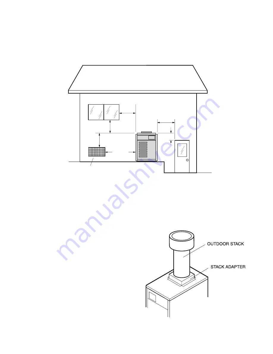
The point from where the flue products exit the heater must be a minimum of four (4) feet below, four (4) feet

horizontally from or one (1) foot above any door, window or gravity inlet to a building.  The top surface of the heater
shall be at least three (3) feet above any forced air inlet, or intake ducts located within ten (10) feet horizontally.

HIGH WIND CONDITIONS (OUTDOOR UNITS ONLY)

In areas where high winds are frequent, it may be necessary to locate the heater a minimum of 3' from high

vertical walls, or install a wind break so the heater is not in direct wind current.

In areas of daily high winds, it may be necessary to replace the outdoor stackless top with a stack adapter in

combination with a wind resistant/weather proof outdoor stack.  See illustration below.

Fig. # 8245.1

The outdoor stack serves the same function as the

low profile stackless top and should be installed in
accordance with the same clearance requirements.

Fig. # 9304

foot

Minimum

foot

Minimum

foot

Minimum

foot

Minimum

foot

Minimum

10 

foot

Minimum

Forced Air Inlet

Summary of Contents for VERSA 155C

Page 1: ... may result causing property damage personal injury or death WHAT TO DO IF YOU SMELL GAS Do not try to light any appliance Do not touch any electrical switch do not use any phone in your building Immediately call your gas supplier from a neighbor s phone Follow the gas supplier s instructions If you cannot reach your gas supplier call the fire department Installation and service must be performed ...

Page 2: ...equirements 9 Base Installation 10 Clearances 12 Combustion Air 12 Venting Connections 14 Gas Supply Connections 15 Plumbing For Water Connections 17 Electrical Wiring 21 SECTION 4 SERVICING INSTRUCTIONS 21 General Location Of Controls 21 Control Adjustments Replacements 22 Pressure Switch 22 High Limit Removal 22 Flame Roll Out Safety Switch 23 Pilot Safety MV Units 23 Pilot Safety IID Units 23 G...

Page 3: ...OR LOSS OF LIFE SECTION 1 START UP PROCEDURES BEFORE START UP BURNERS Clean main burners and air louvers of dust lint and debris Keep heater area clear and free from com bustibles flammable liquids and chemicals Do not obstruct the flow of combustion and ventilating air Fig 8111 0 WATER Water must be flowing through the heater during operation Insure that system is filled with water and have pump ...

Page 4: ... part of the control system and any gas control which has been underwater 1 STOP Read the safety information above 2 Set the thermostat on the lowest setting 3 Turn On Off switch to the Off position 4 Remove heater door panel 5 Push in gas control knob slightly and turn clockwise to Off NOTE Knob cannot be turned from Pilot to Off unless knob is pushed in slightly Do not force 6 Wait 5 minutes to ...

Page 5: ...atically lights the pilot Do not try to light the pilot by hand 5 Remove heater door panel 6 For Honeywell valve Push in gas control knob slightly and turn clockwise to Off Knob cannot be turned to Off unless it is pushed in slightly Do not force For Robertshaw valve Push in and move gas control lever counter clockwise to OFF position 7 Wait 5 minutes to clear out any gas If you then smell gas STO...

Page 6: ...icoagulants should not use spas or hot tubs Pressure Switch Location Fig 8110 1 AFTER START UP Feel the inlet and outlet pipes Outlet pipe should be only slightly warmer than the inlet It should not be hot WARNING Should overheating occur or the gas supply fail to shut off turn off the manual gas control valve to the appliance VISUAL INSPECTION With the heater on remove the door and make a visual ...

Page 7: ...e heater when the pump is shut off NOTE High chemical concentrates from feeders and chlorinators that are out of adjustment will cause very rapid corrosion to the heat exchanger in the heaters Such damage is not covered under the warranty To be followed one month after start up and then semi annually 1 Inspect top of heater and draft hood for soot a sticky black substance around finned tubes and V...

Page 8: ...he heater continuously until higher tempera tures are reached Operating the heater for prolonged periods with pool water below 50 can seriously dam age the heater and is not covered by the warranty For cold climate areas please follow the winterizing proce dures listed WINTERIZING THE POOL SPA HEATER When heaters installed outdoors in freezing climate areas are to be shut down for the winter obser...

Page 9: ...relevationsabove2000feet reduceinput4 for each1000feetabovesealevel ashighelevationreduces combustion performance SECTION 3 INSTALLATION INSTRUCTIONS IMPORTANT NOTICE These instructions are intended for the use of qualified personnel only specifically trained and expe rienced in the installation of this type of heating equip ment and related system components Installation and servicepersonnelmaybe...

Page 10: ...p Stackless Top or Outdoor Stack Unobstructed Vent 6 Left Side 12 Back 12 Back 12 Front Alcove Sides 6 Clearance from Top of Vent Terminal For servicing provide at least 24 in front of the heater for burner tray removal and at least 18 on the back of the heater to inspect and delime the heat exchanger OUTDOORHEATERS These heaters are design certified for outdoor installation when equipped with the...

Page 11: ...take ducts located within ten 10 feet horizontally HIGH WIND CONDITIONS OUTDOOR UNITS ONLY In areas where high winds are frequent it may be necessary to locate the heater a minimum of 3 from high vertical walls or install a wind break so the heater is not in direct wind current In areas of daily high winds it may be necessary to replace the outdoor stackless top with a stack adapter in combination...

Page 12: ...ed in Z 223 1 1988 and any local codes that may have jurisdiction CAUTION Combustion air must not be contaminated by corrosive chemical fumes which can damage the heater and void the warranty a All Air From Inside the Building Each opening shall have a minimum of 151 net free square inches b All Air From Outdoors When air is supplied directly from outside of building each opening shall have a mini...

Page 13: ...he roof more than five feetshouldbesecurelyguyedorbracedtowithstand snow and wind loads We recommend use of insulated vent pipe spacer through the roofs and walls Forprotectionagainstrainorblockagebysnow the vent pipe must terminate with a vent cap which com plies with the local codes or in the absence of such codes latesteditionof theNationalFuelGasCode ANSI Z223 1 The discharge opening must be a...

Page 14: ...nt is recommended A minimum of 7 W C and a maximum of 14 W C upstream pressure under load and no load conditions must be provided for natural gas or a minimum of 12 W C and a maximum of 14 for propane gas GAS PRESSURE REGULATOR The gas pressure regulator is present and sealed at 4 W C for natural gas and 11 W C for propane gas Between the gas valve and the burners is a 1 8 pipe plug The pressure a...

Page 15: ... PLUMBING FOR WATER CONNECTIONS LOCATION The VERSA heater requires water flow and posi tive pressure to fire and operate properly It must therefore be installed downstream of the discharge side of the filter pump A typical installation is plumbed as follows 1 The inlet side of the filter is plumbed directly to the discharge side of the filter pump 2 The outlet side of the filter is then plumbed to...

Page 16: ...ng pool temperatures This narrow range is neededtopreventdamagingcondensationontheburn ers which will occur if the heater runs for any length of time below 100 F It is also needed to inhibit scale formation in the tubes by maintaining temperatures well below accelerated scaling temperatures INTERNAL AUTOMATIC BY PASS VALVE In addition to the Unitherm Governor a built in automatic by pass valve is ...

Page 17: ...mponents MILLIVOLT SYSTEM The Millivolt System Residential Heater is equip ped with a self generating electrical system in which the electric current is provided by means of a pilot generator No external electrical connections are re quired ELECTRONIC INTERMITTENT IGNITION DEVICE SYSTEM IID NOTE When the electrical hookup to the heater requires both 24V and 115V or 240V each input voltage must be ...

Page 18: ...ower supply Connect the red wire to the L2 or second hot leg of the power supply Attach the wire nut to the white wire There should be no connection to the white wire for 240V operation Fig 9241 Heater must be electrically grounded and bonded in accordance with local codes or in the absence of local codes withthelatesteditionoftheNationalElectricalcode ANSI NFPA70 NOTE Input power to the heater 12...

Page 19: ...19 WIRING DIAGRAM MILLIVOLT UNITS Fig 2182e ...

Page 20: ...20 WIRING DIAGRAM 152148 Model 155 IID BL BL BL ...

Page 21: ...ool heater thermostat on the upper front panel of the heater The control center contains an On Off toggle switch and a thermostat The switch functions as a means for turning the heater on or off The thermostat is fitted with a means of limiting the upper temperature limit below the maximum level The knob stop adjustment ring illustrated below is adjust able by loosening the set screw rotating the ...

Page 22: ... Max TWO SPEED PUMPS In some cases the flow on the low speed is insuf ficient to operate the heater This is apparent when the pressure switch cannot be further adjusted or if the heater makes banging noises In these cases the pump must be run at high speed when heating the water CAUTION Do not operate the heater without the functionof a properly adjusted pressure switch HIGH LIMITS The heater is e...

Page 23: ...upply to the heater Remove gas piping to gas valve inlet 2 Disconnect wires pilot tubing and bleed line if required 3 Turn vertical gas pipe from manifold slightly and unscrew gas valve 4 Reverse above procedure to re install MAIN BURNER AND ORIFICE REMOVAL 1 Remove burner drawer See burner drawer removal procedure 2 Remove screws and burner hold down bracket NOTE If the heat exchanger is sooted b...

Page 24: ...ctricityoff closevalvesand relieve pressure 2 Drain heat exchanger 3 Remove retainer plug located under outlet pipe connection 4 Remove spring and replace old U G with a new U G 5 Reverse above procedure to re install Fig 8128 0 GASKET U G RETAINER PLUG SPRING FIig 8071 0 To test the operation of the Unitherm Governor place in hot water over 110 F and watch for move ment against spring If there is...

Page 25: ...ctor off Remove V baffles over tube s to be replaced Ifnopipeunionshavebeenprovided usethe header as a union remove the flange nuts off the inlet outlet header break gas connection and slide heater away from piping to allow room to work Pull wedge clips out of control wells and remove sensing bulbs Lift heat exchanger straight up and out Inspect header gaskets at this time Unless sev ered they are...

Page 26: ... 150 400 PPM maximum Sooting High flow rates Reduce by adding manual bypass valve and adjust by putting thermometer in header 1 4 NPT drain opening Set bypass so thermometer reads between 105 and 110 F U G Inoperative Check movement by putting in hot water 110 F or higher If no movement replace Air starvation Refer to installation instructions Improper venting Follow recommended installation instr...

Page 27: ...ner goes out when main burner lights or when gas valve knob is released If burner does not remain lit attach millivolt meter and read pilot output If below 500mV check gas pressure Also check for insects or debris in the pilot burner If main burner fires remove jumper Replace gas valve If main burner does not fire remove jumper Remove both TH wires from gas valve Relight pilot If pilot burner stay...

Page 28: ... pilot gas if pilot fails to light To reset interrupt power to heater Intermittent Pilot System TROUBLESHOOTING HONEYWELL S8600 NOTE Before troubleshooting familiarize yourself with the start up and checkout procedure Check line voltage power low voltage transformer limit controller thermostat controller and wiring Pull ignition lead and check spark at module Spark Okay YES Check ignition cable gr...

Page 29: ... 5 V Check transformer 120 V supply correct as necessary TEMPERATURE 105 106 F Control ok RESISTANCE O OHMS SHORT CIRCUIT Check system for shorted wires or open circuits Replace sensor if necessary MEASURED AND ESTIMATED RESISTANCE DON T MATCH Replace sensor Reconnect all leads and check out system Check voltage at 24 V terminals VOLTAGE BETWEEN 21 5 28 5 V Set control to max temperature After 2 3...

Page 30: ...andard company warranties must be properly tagged with RAYPAK return parts tag completely filled in with the heater serial number model number etc and shipped to the Company freight prepaid If determined defective by the Company and within warranty the part will be returned in kind or equal substitution freight collect Credit will not be issued RAYPAK INC 31111 Agoura Road Westlake Village CA 9136...

Page 31: ...31 ...

Page 32: ...32 ...

Page 33: ...33 ...

Page 34: ... 1234567 1234567 1234567 1234567 1234567 1234567 1234567 1234567 1234567 1234567 1234567 1234567 1234567 1234567 1234567 1234567 1234567 1234567 1234567 1234567 1234567 1234567 1234567 1234567 1234567 1234567 1234567 1234567 1234567 1234567 1234567 1234567 1234567 1234567 1234567 1234567 1234567 1234567 1234567 1234567 1234567 1234567 1234567 1234567 1234567 1234567 1234567 1234567 1234567 1234567...

Page 35: ... 1500 FAX 800 872 9725 Raypak Canada LTD 2805 Slough Street Mississauga Ontario Canada L4T 1G2 905 677 7999 FAX 905 677 8036 Raypak Australia Pty Ltd 7 Geddes St Mulgrave Victoria Australia 3170 6139 560 4944 FAX 6139 560 4974 Litho in U S A www raypak com ...

Reviews: