17
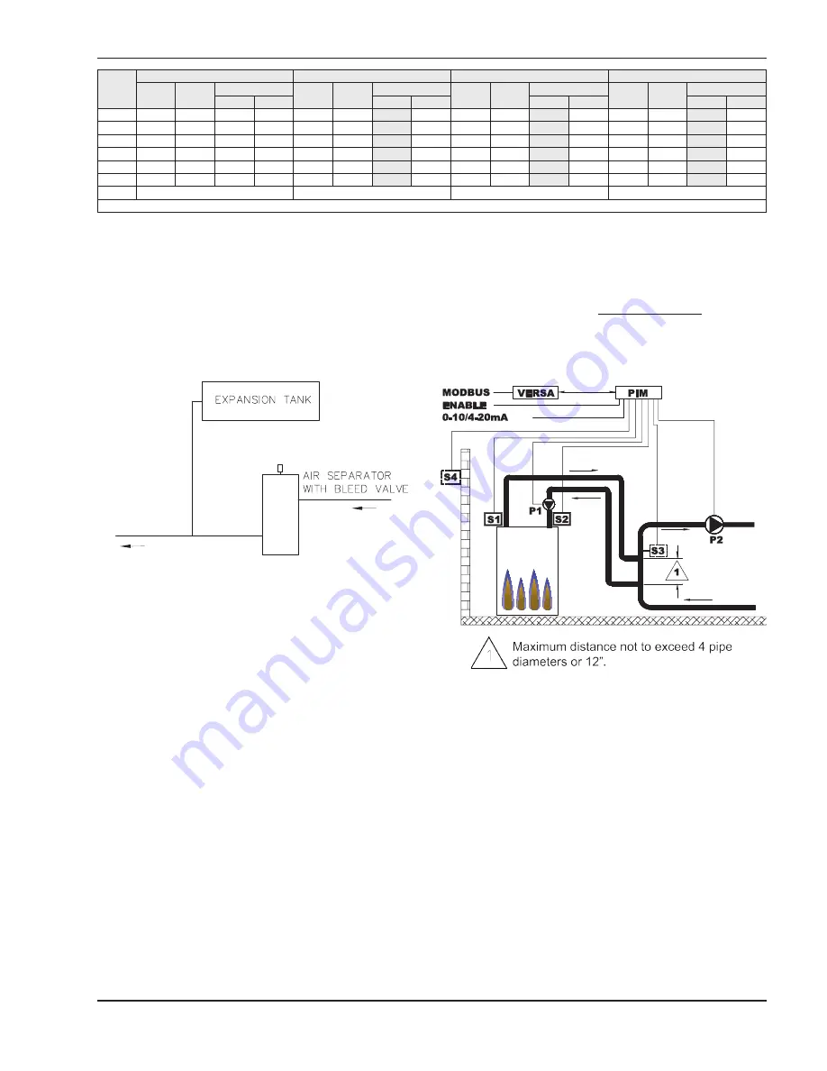
Fig. 17: MODE 1 - Single Boiler with
Primary/Secondary Piping
Table F: Boiler Rates of Flow for Various System Pipe Sizes
Chart above represents performance capacity for injection pump as provided with the unit. Pipe size determined by velocity not to exceed
7.5 ft per sec.
Fig. 16: Air-Separation/Expansion Tank
Three-Way Valves
Three-way valves intended to regulate system water
temperatures by reducing flow in the boiler should not
be used. Raypak heaters are high-recovery, low-mass
heaters which are not subject to thermal shock.
Applications & Modes
The VERSA IC Control system is designed for a wide
range of applications. The installer/design engineer
should refer to the following Modes to determine which
best fits the intended application and functionality for
the unit being installed.
Type H models of XTherm have three modes available
to them to address the various applications the units
can be applied to. Type WH units will only have the
WH configuration available to them for use with pota-
ble water applications when directly connected to a
hot water storage tank. Type P units will only have the
pool configuration.
For detailed information on the VERSA IC control sys-
tem, see Catalog 5000.72. This manual can be found
in the document library at www.raypak.com.
Min System Flow = 120% of Max Boiler Flow
Mode 1 (Type H Units Only)
Sys Ret
Temp
(F)
Model 2505 (30F Sys Delta T)
Model 3005 (30F Sys Delta T)
Model 3505 (32F Sys Delta T)
Model 4005 (33F Sys Delta T)
Supply
Temp (F)
Sys Flow
GPM
Pipe max eq ft
Supply
Temp (F)
Sys Flow
GPM
Pipe max eq ft
Supply
Temp (F)
Sys Flow
GPM
Pipe max eq ft
Supply
Temp (F)
Sys Flow
GPM
Pipe Max eq ft
3”
4”
3”
4”
3”
4”
3”
4”
60
144
57
230
450
146
66
110
148
76
100
144
90
100
80
144
74
230
450
146
86
110
148
98
100
144
119
100
100
144
108
230
450
146
124
110
148
139
100
144
173
100
120
150
158
230
450
150
190
110
152
208
100
153
230
100
140
170
158
230
450
170
190
110
172
208
100
173
230
100
160
190
158
230
450
190
190
110
192
208
100
193
230
100
∆P MAX
158GPM @ 12.5 ft.hd.
190GPM @ 2.3 ft.hd.
208GPM @ 2.5 ft.hd.
230GPM @ 2.95 ft.hd.
HIGH FIRE CONDITIONS
Fig. 16.
This mode selection is for hydronic heating systems
with single or multiple boilers (Maximum 4 boilers) in
primary/secondary piping configuration with or without
Outdoor Air Reset (S4). The system temperature
is controlled by the System sensor (S3). The Boiler/
Injection Pump (P1) runs during any call for heat.
The System Pump (P2) runs whenever the system is
enabled for heating and the outdoor air temperature is
lower than the warm weather shut down (WWSD) tem-
perature setting (if utilized). The Boiler/Injection Pump
(P1) is delayed “off” as user defined in the
BOILER
menu and the System Pump (P2) is delayed “off” in
the
ADJUST
menu.


