


48
between:
L1 - Ground (≈120 VAC)
L2 - Ground (≈120 VAC)
L1 - L2 (≈240 VAC)
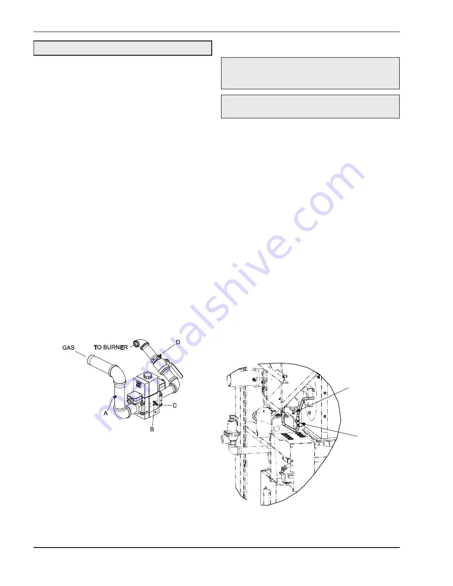
Attach Manometers to Measure Pressures
1. Turn off main gas valve.
2. Attach (1) 12” scale manometer to an upstream
bleedle valve on the gas supply pipe to the heater
(Measure point “A” in Fig. 55).
3. Attach (1) 24” scale manometer to the manifold
pressure tap located on the shutoff valve down-
stream of the firing valve (Measure point “D” in
Fig. 54).
4. Attach (1) 12” scale manometer on the fan suc-
tion pressure hose. Pull black cap from the air
pressure tee as shown in Fig. 56 and connect the
manometer. NOTE: Retain caps for reinstallation
later.
Check Gas Supply Pressure
1. Slowly turn on main gas shut-off valve.
2. Read the gas supply pressure from the manom-
eter; minimum supply pressure for natural gas is
4.0 in. WC, recommended supply is 7.0 in. WC,
mini-mum supply pressure for propane gas is
4.0 in. WC, recommended supply is 11.0 in. WC
(dynamic readings, full fire input).
3. If the gas pressure is greater than 14.0 in. WC,
turn off the main gas shut-off valve, upstream of
the heater.
Start-Up
1. Turn power on.
2. Turn on the heater, wait approximately 15 sec-
onds after the blower starts, the igniter should
start to glow (observable through the observation
port located at the front, below the gas valve).
Look into the sight glass located just below the
gas valve near the front of the unit to check igniter
operation. Gas valve should open in 45-60 sec-
onds.
3. The heater ignites at 30% to 40% of full rate (as
indicated on the LCD display of the temperature
controller located behind the front panel).
4. If the burner fails to light on the first trial, it will try
for ignition up to three times before going into lock-
out with the standard ignition module. If the heater
is equipped with the optional single-try ignition
module, it will go into lockout.
5. Wait until the controller indicates 100% on the
firing rate display screen (approximately 30 sec-
onds).
Fig. 55: Gas Pressure Measurement Locations
NOTE:
The values in Tables U and W represent the
conditions when the heater is at full firing rate at sea
level.
WARNING:
Do not turn on gas at this time.
NOTE:
Pressure and combustion data are provided
with the heater.
MANIFOLD TAP
AIR PRESSURE
TEE
Fig. 56: Air Pressure Tee


