background image

DHG0000004 RB Universal SR1000™ Installation Manual

Heavy rain, snow or ice may also interfere 

with the signal reception.  Stray signals from 

radio or television broadcast towers may also 

affect the satellite signal.

3.5 Standing Water Interference 

When a vehicle is parked, rain and morning

dew may collect on the radome of the 

SpeedRay™ 1000.  This may cause 

interference with satellite reception.  Once 

the vehicle is in motion, any standing 

water on the antenna should roll off and the 

interference resolved.  Clean the radome 

with a soft, clean cloth if necessary.  Some 

aftermarket water repellents are also 

available to help reduce rain and dew from 

building up on the antenna.  

3      Receiving Mobile Satellite TV

Summary of Contents for SpeedRay 1000

Page 1: ...For Universal Applications 2006 RaySat Inc All rights reserved DHG0000004 RB SpeedRay and RaySat are registered trademarks of RaySat Cyprus Ltd ...

Page 2: ...Interference 9 4 SpeedRay 1000 Components and Parameters 10 4 1 System Components 10 4 1 1 Antenna 10 4 1 2 Indoor Unit IDU 10 General System Parameters 11 5 Installing the Antenna onto a Roof Rack 12 5 1 Shipping Restraint 13 5 2 Clamp Design 13 5 3 Installation Procedure 14 6 Installing the Indoor Unit IDU and Satellite Receiver 18 6 1 Placement of IDU and Receiver 18 6 2 Installing the IDU 18 7...

Page 3: ...mpliance 34 Most television audio and video programming is protected by copyright and other laws Recording or rebroadcasting of paid or other public display may violate such laws and result in civil and or criminal penalties Consumer is responsible for subscribing to a satellite broadcast service and for all subscription costs Unauthorized decoding of broadcast signals may violate applicable laws ...

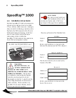
Page 4: ...r antenna and indoor unit in the boxes provided on this page before installation Antenna Serial Part Part serial numbers are located on the bottom of the antenna near the TNC connector Indoor Unit IDU Serial Part Part serial numbers are located on the bottom of the IDU DO NOT VIEW from Drivers Seat Do NOT view from the driver s seat WARNING DO NOT INSTALL AN ACTIVE MONITOR IN RANGE OF THE VEHICLE ...

Page 5: ...ury CAUTION Alerts installers and customers to possible electrocution hazards TOOLS INSTALLATION Marks the areas requiring special tools and installation procedures KEY NOTES Helpful tips are indicated with a key They offer key suggestions on efficient installation procedures to get the maximum performance from your system 1 3 Various Hardware Kits The SpeedRay 1000 system is comprised of many par...

Page 6: ... TOOLS INSTALLATION Verify that the roof rack is in good condition and can support the 24 kg antenna prior to installation Seek professional assistance to tighten or adjust the mounting brackets as required for safety and safe operation of the vehicle WARNING There are no user accessible parts Repairs to any component of the SpeedRay 1000 should be performed only by RaySat authorized technicians K...

Page 7: ... Evidence of unauthorized repairs or tampering will void the warranty CAUTION Do not open or remove the cover of the receiver antenna or indoor unit IDU to avoid exposure to dangerous voltage CAUTION To avoid fire or electrical shock by the receiver indoor unit or other components do not expose them to rain or moisture this does not include the weatherproof antenna The IDU and receiver s ventilati...

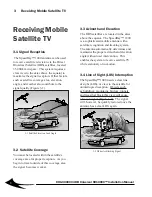
Page 8: ...ntenna with a satellite recognition and tracking system The antenna automatically determines and maintains the proper azimuth and elevation angle without user intervention This enables the system to receive satellite TV while stationary or in motion 3 2 Satellite Coverage You must be located within the satellite s coverage area for proper reception As you begin to travel outside of this coverage a...

Page 9: ... a vehicle is parked rain and morning dew may collect on the radome of the SpeedRay 1000 This may cause interference with satellite reception Once the vehicle is in motion any standing water on the antenna should roll off and the interference resolved Clean the radome with a soft clean cloth if necessary Some aftermarket water repellents are also available to help reduce rain and dew from building...

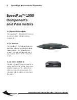
Page 10: ...e electronics within a weather tight radome plastic housing It is mounted to the vehicle s roof rack and connected with a single coaxial cable to the IDU inside the vehicle 4 1 2 Indoor Unit IDU The IDU supplies power and commands to the SpeedRay 1000 antenna This device allows for selection of the satellite from which you wish to receive a signal It is collocated with the satellite receiver insid...

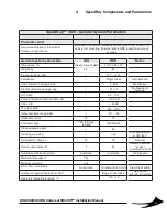
Page 11: ...al Elevation Beam Coverage deg 20 70 Mechanical Electrical G T dB K 6 0 10 0 Cross Polarization Discrimination dB 15 0 dB PSLL dB 6 0dB IF output MHz 950 2150 Output dynamic range dBm 70 30 Impedance ohm 75 75 Connector Type TNC F type female TNC female Tracking speed deg s 60 Tracking error deg 0 6 With acceleration at 360 sec 2 External DC voltage V 12 30 Nominal Power consumption W 7 52 Assumed...

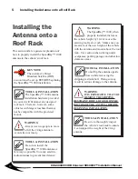
Page 12: ...NNING INSTALLATION TOOLS INSTALLATION Do not flip the antenna upside down while removing the shipping restraint bolt Doing so may result in serious damage to the antenna TOOLS INSTALLATION Be sure to thoroughly inspect the vehicle s roof rack to ensure it can support the weight of the 24 kg antenna TOOLS INSTALLATION The SpeedRay 1000 antenna installation hardware provided in your kit will fit alm...

Page 13: ...ert webring plug Bottom of antenna WARNING Be sure to use only the hardware provided in the hardware kit Substituting any hardware or making any modifications may result in an improper and unsafe installation Install all hardware according to this guide TOOLS INSTALLATION Use a towel or moving cloth to protect the roof of the vehicle while installing the antenna Figure 5 3 Bracket spacer between b...

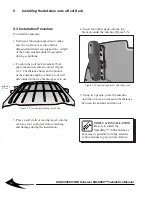
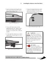
Page 14: ...size bracket spacer to use 5 Using two people place the antenna onto the roof rack to measure the distance between the antenna and the roof 3 Place a soft cloth or moving towel onto the vehicle s roof to protect from scratching and damage during the installation Figure 5 5 Top mounting bracket with rubber pad 4 Insert the rubber pads onto the top brackets under the antenna Figure 5 5 5 Installing ...

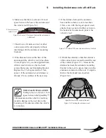
Page 15: ...ar of vehicle Figure 5 8 Centering the antenna on roof Equal distance to the center of the roof Figure 5 6 Leave a 2 5cm space between the antenna and vehicle roof 1 Clearance To Vehicle Roof 2 5cm clearance to vehicle s roof 7 Check to see if sun moon roof or other vent system will work properly without interfering with the antenna or mounting brackets 8 If the distance between the base of the an...

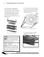
Page 16: ... bracket and rubber pad Figure 5 9 5 Installing the Antenna onto a Roof Rack WARNING Ensure that the mounting brackets are secured adequately so that as much of the crossbar s surface is covered by the top and bottom clamps as possible Failure to do so may cause antenna to become unstable TOOLS INSTALLATION It is highly recommended that a low strength liquid thread lock be applied to the head scre...

Page 17: ...to the roof rack complete a thorough inspection of all four brackets to ensure the antenna is secure and stable 15 Secure the bottom bracket with the appropriate head screws Make sure that as much of the rubber on the mounting brackets cover as much of the crossbars as possible 16 Fully tighten the end head screw with the supplied Allen wrench Figure 5 13 Do not overtighten Figure 5 12 Inserting h...

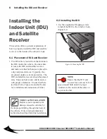
Page 18: ...U and satellite receiver should be placed away from any heat source and in an area with proper ventilation Ensure that there is at least 5cm of space around both units for ventilation and connection of cables NOTE Ensure that the IDU and receiver have at least 5cm of space around both units for proper ventilation Do not stack the units on top of each other 6 2 Installing the IDU 1 Use the supplied...

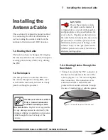
Page 19: ... vehicles by the improper drilling or installation of antenna cable through the roof or body of the vehicle 7 2 1 Routing Cables Through the Rear Hatch 1 Connect one end of the TNC connector to the back of the antenna at the rear of the vehicle Figure 7 1 Do not overtighten this connection The connection at the antenna should be weatherized and protected from outside elements through the use of we...

Page 20: ...crossbars with tie wraps In appropriate situations you may use self adhesive cable straps to secure the cable to the vehicle Figure 7 3 2 Run the cable along the roof rack of the vehicle back to the hatch With the hatch open route the cable behind the hatch to inside the vehicle Figure 7 2 TOOLS INSTALLATION Only a trained automotive installer should run cable or remove the vehicle s headliner Imp...

Page 21: ...Routing cable between two panels 7 2 2 Routing Cables Through Two Panels Another technique for bringing the antenna cable into an existing POE is to route the cable between two body panels of the vehicle Figure 7 4 The antenna cable may be small enough for certain vehicles Take every precaution to protect the vehicle from body damage and water infiltration If the space between two body panels is t...

Page 22: ...roach depending on existing vehicle accessories WARNING Wires sheathed in brightly colored plastic PVC usually yellow or orange are indicative of airbag circuits Do NOT disturb these wires If in doubt call Customer Service before continuing Once all of the system cables have been connected the following steps will inform you of different methods of connecting power from the vehicle to the IDU WARN...

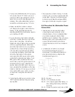
Page 23: ...t the vehicle is turned off Remove the negative cable from the battery Verify total disconnection by attaching the DMM to both battery posts to get a reading of 0 00V 5 Locate the in line fuse holder included in the kit Lift the protective cap off and remove the 15 amp fuse Cut the fuse holder wire loop in half so that you end up with two equal length ends Attach one end of the fuse holder as clos...

Page 24: ...pplications using 230VAC an additional 12V to 230V inverter must be used Wire in an additional relay for a total of two relays to provide power to the inverter A 20A fuse should be installed between pin 30 on the relay and the inverter Figure 8 2 Figure 8 2 Relay Diagram for 230V power 8 Connecting the Power ...

Page 25: ...ff using the power switch located on the back 2 WAN WLAN Indicators This feature is used for two way data communications 3 TV DATA Indicators This button will switch the IDU configuration between TV and data modes of operation 4 LCD Screen Used for verification of system status and troubleshooting 5 Up Down Arrows These buttons are used to scroll through menu options 6 Esc This button is used to b...

Page 26: ...switch loca ted on the back of the IDU 9 Operating the Antenna Controller CAUTION Only use the inverter on the back of the IDU for providing power for the satellite modem DO NOT plug any other electronic equipment or appliances into this outlet Doing so may overload and damage the IDU Figure 9 2 Antenna controller connections From Antenna To Satellite TV Receiver To Power Supply Ethernet for Contr...

Page 27: ...thray will now go through the Initialization Acquisition and Checking process 4 Once the antenna locks onto the satellite the LCD screen will show Tracking Figure 9 4 Figure 9 4 Acquiring the satellite 9 5 Front Panel Menu Options Your antenna controller has four menu options for inputting parameters and troubleshooting Pressing the Enter button will bring up the following menus 1 Setup 2 Install ...

Page 28: ... antenna controller 2 Satellite Database Displays the current satellite database 3 Satellite Recognition Displays the current recognition software version 4 IDU SN Displays the serial number of the antenna controller 5 ODU SN Displays the serial number of the antenna 6 Status Displays status codes for both the antenna and controller 7 Temperature Displays temperature readings for both the antenna ...

Page 29: ...of the cable Trim the braid back 8 2mm from the end Strip the foam insulator back 4 7mm from the end of the cable 2 Slide the ferrule over the RG58 cable 4 Solder the center pin to the cable s center conductor at the hole on the pin 5 Fold the braid back from the cable 6 Slide the Connector onto the cable Ferrule Step 4 Step 3 Step 2 Step 5 Step 6 TNC connector Step 7 Step 1 8 2mm 4 7mm 16 4mm 7 S...

Page 30: ...oper wiring to the vehicle s power source Verify 12 VDC is being supplied to the IDU BLACK OR BLUE SCREEN ON TELEVISION Verify that the IDU and receiver are powered on Ensure that all video connections are installed Check for proper television settings SNOWY TELEVISION PICTURE Verify that television settings are correct Correct channel configuration channel 3 4 or A V input Make sure video cables ...

Page 31: ...e satellite from the Setup Menu of the receiver CERTAIN CHANNELS DO NOT WORK OR ONLY PREVIEW CHANNELS ARE VISIBLE Verify channel package with satellite TV provider Check the availability of local channels in the subscriber s area Ensure proper activation of satellite receiver REMOTE CONTROL DOES NOT WORK Ensure proper placement of IR transmitter if RF to IR converter has been installed Install new...

Page 32: ...nal strength Correct activation of Receiver Local channels are available in limited area check availability Place the IR transmitter according to the manual OPTIONAL System does not power on X X X X X Indoor Unit does not lock on satellite X X X X X X System continually resets X X Black or blue screen on TV X X X X Snowy television picture X X X X Intermittent picture for short intervals X X X X P...

Page 33: ... Inc 8460 C Tyco Road Vienna VA 22182 This product has been tested by an FCC Laboratory in April 2005 and was found to be in compliance with the relevant sections of the following standard FCC CFR 47 Part 15 Subpart B ICES 003 Refer to Test Report No RST180505 RST170505 for detailed test results Industry Canada File No IC4808 Certificate Number RST180505 RST170505 ...

Reviews: