T7 Installation & User Manual
25
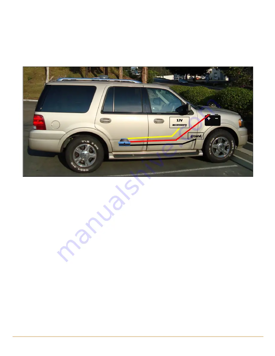
Figure 10-1 Electric connections
10.1 Connecting to Switched/Accessory Power
The system is designed to work with the vehicle’s accessory switch. Failure to follow these procedures could
result in system failure or vehicle failure.
1. The power cable has a ground wire (black), an accessory wire (yellow) and a power wire (red) (Figure 10-1).
2. Locate a suitable or authorized ground point within the vehicle. Keep the ground wire as short as
possible.
The power cable should NOT be connected to the receiver at this time.
3. Locate a switched/accessory wire within the vehicle. Verify with a DMM that the 12V accessory wire
reads at least 11V while in the ‘accessory’ position; 0.00V when starting the vehicle; and 13.2 - 14.8V while
the engine is running. This will confirm that you have located the 12V switched accessory wire.
4. Make sure that the vehicle is turned off and remove the positive cable from the vehicle’s battery.
5. Route and connect the ground wire to the vehicle ground point. Ensure there is a good connection.
6. Route and connect the accessory wire from the receiver location to the located switched/accessory wire
of the vehicle.
7. Route and connect the power wire from the receiver location to the positive terminal of the vehicle’s
battery. Take special care when routing this wire through the fire wall. Use authorized grommets where
possible. If no grommet is available, be sure to protect the wire from being spliced or cut from continuous
wear along the POE.
8. Insert the power plug into the receiver.
9. Reconnect the positive terminal of the vehicle’s battery.


