background image

Installation

3


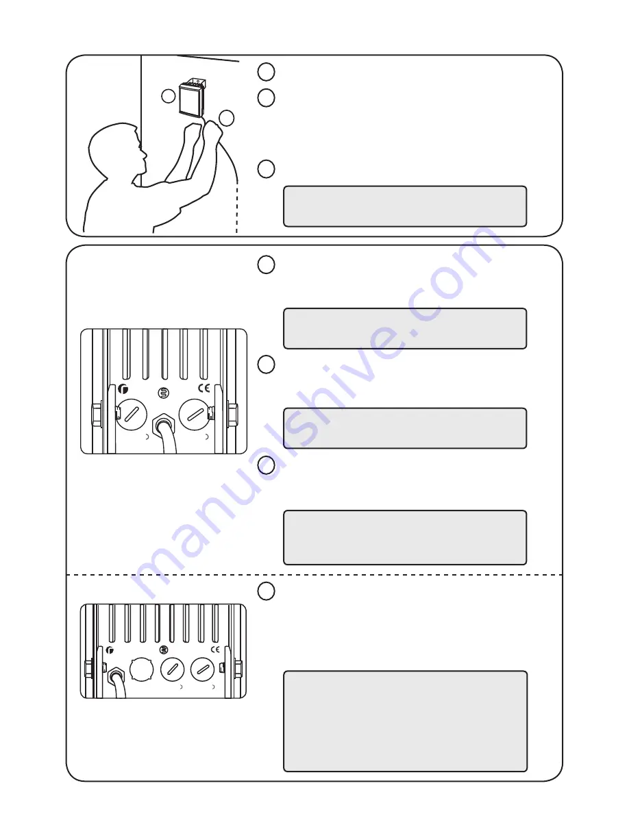
Mount illuminator 

Connect Illuminator to low voltage power 
supply: Installers can extend or reduce lead 
length using appropriate cable and weather 
proof box

Input 12-24V DC/ 24V AC

2

3

1

RM/RL F 100 only: 

Telemetry input and photocell following 
contact. Remove cap on telemetry and 
photocell following contact connector. 
Connect additional cable loom (see below).

5

7

6

4

1

2

Adjust Photocell sensitivity. Remove the cover 
and turn the ‘photocell adjust’ to alter photocell 
sensitivity to ambient lighting condition.

Photocell following contact, volt free relay 
contact - normally open (day) to normally 
closed (night).

Clockwise=

more

 sensitive

Anticlockwise=

less

 sensitive

RM/RL F 25 & 50 only

Orange 

and

 brown 

wires =

Photocell following contact

RM/RL F 100 only

Blue

 and 

black

 wires =

telemetry connection for remote operation

White

 and 

brown

 wires = 

photocell following contact connection

Adjust Power to alter light intensity.  
Remove the cover and turn the ‘power adjust’  
to alter the intensity of the light level.

Clockwise=

increase

Anticlockwise=

decrease

Note:    Red =

positive

             Black = 

negative

Power 

in

Made in UK

P-cell

adjust

-

+

Power

adjust

-

+

Power

adjust

-

+

Power 

in

Made in UK

P-cell

adjust

-

+

Telemetry P/C 

Contact

Optional Set-up (if required)

Note: Factory set to max. power

RM/RL F 25 & 50

RM/RL F 100 only

Summary of Contents for RL F 25

Page 1: ...amera and point towards scene 2 Adjust vertical and horizontal position of lamp to ensure full field of view illuminated 3 Tighten all fixings Package Contents 1 Illuminator including mounting bracket...

Page 2: ...owing contact Power adjust Power in Made in UK P cell adjust Telemetry P C Contact Back of Unit Command and Control Technology DC AC Black wire Red wire DC AC Black wire Red wire RM RL F 25 50 Cables...

Page 3: ...ontact volt free relay contact normally open day to normally closed night Clockwise more sensitive Anticlockwise less sensitive RM RL F 25 50 only Orange and brown wires Photocell following contact RM...

Page 4: ...illuminator adjacent to camera and point towards scene Optional night set up for optimum image performance 4 Reduces performance May cause hot spots Best performance Camera 1 Adjust vertical and horiz...

Page 5: ...rawings Not to scale Standard Bracketry Optional Bracketry 25mm 1 12 5mm 0 5 47mm 1 9 RM RL F 25 25mm 1 36mm 1 4 72mm 2 8 RM RL F 50 25mm 1 52mm 2 104 5mm 4 1 RM RL F 100 Wall Mount Dome Mount Ptz Mou...

Page 6: ...mption 35W max 25W max 12W max Input 12 24V DC 24V AC 12 24V DC 24V AC 12 24V DC 24V AC Current 2 6A 12V or 1 3A 24V 1 5A 12V or 0 75A 24V 1A 12V or 0 5A 24V Weight 1 4kg 1 0kg 0 5kg Environment IP66...

Page 7: ...eck lamp current remove ve red lead from power supply and connect multimeter set to 10A in line with the lamp One lead of multimeter in common COM other lead into 10A socket of multimeter set multimet...

Page 8: ...UK Europe T 44 0 1670 520055 F 44 0 1670 819760 sales rayteccctv com Americas Toll Free T 1 888 505 8335 ussales rayteccctv com www rayteccctv com...

Reviews: