background image

Raytech USA, Inc.  All rights reserved

Ver. 1.13

9

OPERATION INSTRUCTIONS:

8

0

WARNINGS!

BEFORE OPERATING TEST EQUIPMENT READ ALL SAFETY WARNINGS.

TR-1 & TR-1P Operating Instructions:

If you are new to transformer turns ratio testing, please review the entire manual carefully before operating this
equipment. If you have any questions please do not hesitate to contact your nearest representative or Raytech USA.

All selections and data input are accomplished through the Front Panel Rotary Digipot.
WARNING: Do not push on the display screen.

Step by step Instructions:

Open the instrument case. Connect the measuring leads to the 9 pin Black front panel connector. This is a Twist -
lock style connector marked "To Test Object". Attach the spade end of the safety ground lead to TR-1 and the clip
side to a good known ground / earth point.
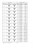
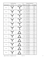
Connect the test lead clips to the proper terminals of a transformer.

Note:

The “H” leads are always connected to the highest number of turn

s on all

transformers and the “X” Leads are

always connected to the lowest number of turns. The TR-1 & TR-1P is a very clever system and will always check
to make sure that this is done correctly.

Note: The Ratiometer will not operate unless connected to a transformer.
The word "GO" will appear when the leads are attached to a transformer. This Ratiometer sense circuit can be
checked by connecting all of the measuring lead clips of the test set all together. The "GO" Will appear in the test
screen.  No Ratio test can be performed however.

Turn the system on by pressing the Rotary Digipot down.
Wait for the system to initialize and perform self checks and auto-calibration.

Select the correct Test Voltage:
Turn the Rotary Digipot

and highlight "SETUP”.

Press down on the Digipot. "UTEST" will be high lighted. Select

the proper test voltage by continuously pressing the Digipot down.
The following are the current choices:
40V: For most Potential (Voltage) Transformers. Offers the highest accuracy.
10V: For most Potential (Voltage) Transformers. Increases current output. Offers high accuracy.
5V: For most Transformers. Increases current output. Can be used on some Current transformers. High accuracy.
1V: For Current Transformers. Highest current output. Recommend using on Current transformers.
CT Auto: For Current Transformers only. Automatically detects and selects the highest output power available in
the system. CT AUTO mode is for use with current transformers only. Not to be used with potential transformers.

After selecting the Test Voltage, Exit that menu by highlighting "EXIT" with the Digipot and press down.

If properly connected to a transformer "GO" should appear in the test screen. Highlight and press "GO" and the test
set will test that ratio and automatically store the result in the next available memory location.

You may print the results now or you may recall the saved values from memory and print at a later time.

Summary of Contents for TR-1

Page 1: ...S 2nd Street Perkasie PA 18944 USA Tel 888 4 THE SPY Tel 267 404 2676 Fax 267 404 2685 Single Phase Battery Operated Automatic Transformer Turns Ratiometer Test System Model TR 1 Model TR 1P Instruct...

Page 2: ...s 1 0 2 Uncrating Procedure 2 0 3 Introduction 3 0 4 Technical Specifications 4 0 5 Front Panel Description 5 0 6 Typical Display Screens 6 0 7 Transformer Ratio Testing 7 0 8 General Notes on Testing...

Page 3: ...s BEFORE APPLYING POWER Make sure the transformer to be tested is cleared and removed from operation GROUND THE INSTRUMENT To minimize shock hazard the instrument must be connected to a properly groun...

Page 4: ...rd TR 1P If any of the above items are missing or damaged please contact your local representative or Raytech USA Inc immediately RAYTECH USA Toll free service support telephone 1 888 4 THE SPY Note T...

Page 5: ...readings on site with laboratory precision The TR 1 TR 1P applies a preset test voltage on the HIGH winding side of the transformer and measures back through the LOW side of the transformer The result...

Page 6: ...Instruction Manual and instrument carry case with shoulder strap TR 1P includes paper refills for the panel mount printer TR 1 FEATURES Automatic measurements of Turns Ratio and Current Automatic det...

Page 7: ...inter allows the user to print out stored results or current results The single button on the printer is for Form Feed To tear paper pull paper towards the front of the instrument against the serrated...

Page 8: ...ge Selector Test Voltage Selector CT Mode Screen 40V selected Screen CT Auto selected License Screen Setup Screen Test in progress After test display Firmware is 0 85 Serial No is 272 100 Pre test scr...

Page 9: ...ormer For example The High Side Winding may contain 960 Turns Low Side Winding 440 Turns Therefore Note 3 Phase Transformers Turns Ratio Voltage Ratio are usually different IMPORTANT NOTE 1 Hooking up...

Page 10: ...ecked by connecting all of the measuring lead clips of the test set all together The GO Will appear in the test screen No Ratio test can be performed however Turn the system on by pressing the Rotary...

Page 11: ...gh the X leads The X leads must always have lower voltage than the H leads or an error will be displayed When testing Current transformers take care that the test leads are correctly attached In certa...

Page 12: ...or group number of 3 would have a phase displacement of 3 x 30 or 90 The low side winding has a lagging displacement with respect to the high side winding PHASE The transformer phase that is being tes...

Page 13: ...2 X0 A H1 H0 X0 X1 YN yn 6 B H2 H0 X0 X2 C H3 H0 X0 X3 A H1 H0 X2 X0 YN yn 8 B H2 H0 X3 X0 C H3 H0 X1 X0 A H1 H0 X0 X3 YN yn 10 B H2 H0 X0 X1 C H3 H0 X0 X2 A H1 H0 X1 X2X3 YN y 0 B H2 H0 X2 X1X3 C H3...

Page 14: ...H1 X0 X2 C H3 H2 X0 X3 A H1 H3 X2 X0 YN zn 7 B H2 H1 X3 X0 C H3 H2 X1 X0 A H1 H3 X0 X3 YN zn 9 B H2 H1 X0 X1 C H3 H2 X0 X2 A H1 H3 X1 X0 YN zn 11 B H2 H1 X2 X0 C H3 H2 X3 X0 A H1 H0 X1 X2 YN d 1 B H2...

Page 15: ...H1 X1 X3 C H3 H2 X2 X1 A H1 H3 X3 X1 D d 6 B H2 H1 X1 X2 C H3 H2 X2 X3 A H1 H3 X2 X1 D d 8 B H2 H1 X3 X2 C H3 H2 X1 X3 A H1 H3 X2 X3 D d 10 B H2 H1 X3 X1 C H3 H2 X1 X2 A H1 H3 X1 X0 D yn 1 B H2 H1 X2...

Page 16: ...X1X3 A H1 H3 X2X3 X1 D y 7 B H2 H1 X1X3 X2 C H3 H2 X1X2 X3 A H1 H3 X2 X1X3 D y 9 B H2 H1 X3 X1X2 C H3 H2 X1 X2X3 A H1 H3 X1X2 X3 D y 11 B H2 H1 X2X3 X1 C H3 H2 X1X3 X2 A H1 H2H3 X1 X0 D zn 0 B H2 H1H3...

Page 17: ...X0 X1 Y yn 6 B H2 H1H3 X0 X2 C H3 H1H2 X0 X3 A H1 H2H3 X2 X0 Y yn 8 B H2 H1H3 X3 X0 C H3 H1H2 X1 X0 A H1 H2H3 X0 X3 Y yn 10 B H2 H1H3 X0 X1 C H3 H1H2 X0 X2 A H1 H2H3 X1 X2X3 Y y 0 B H2 H1H3 X2 X1X3 C...

Page 18: ...2 X2 X0 A H1 H2H3 X0 X1 Y zn 7 B H2 H1H3 X0 X2 C H3 H1H2 X0 X3 A H1 H2H3 X2 X0 Y zn 9 B H2 H1H3 X3 X0 C H3 H1H2 X1 X0 A H1 H2H3 X0 X3 Y zn 11 B H2 H1H3 X0 X1 C H3 H1H2 X0 X2 A H1 H2H3 X1 X2 Y d 1 B H2...

Page 19: ...ement to use this calculation chart is that the connections to the transformer be made exactly as indicated in the previous charts See pages 10 to 15 Config Multiply reading With this factor to get Tu...

Page 20: ...sible causes for these messages 1 Faulty transformer under test 2 Low inductive low resistive loads such as windings without cores 3 Device under test was not properly demagnetized ERRATIC OR ERRONEOU...

Page 21: ...e responsibility of purchaser This warranty shall not apply to any accessories parts or materials not manufactured or supplied by RAYTECH USA Inc Equipment must be returned prepaid with a Return Mater...

Reviews: