


Raytech USA, Inc. All rights reserved
Ver. 1.13
10
CURRENT TRANSFORMER TESTING:
9
–
0
Current transformers are, in effect, an opposite wound voltage transformer. This basically means that the largest
number of windings are on the “
X
” (low current) side of the current transformer.
Therefore, the TR-1 "H" test leads
connect to the low current side (ie.. 5A or 1A) and the TR-1 "X" test leads connect to the high current side.
The TR-1 & TR-1P apply
a test voltage from the “
H
” leads and measure back through the “
X
” leads. The “
X
” leads
must always have lower voltage than the “
H
” leads or an error will be displayed.
When testing Current transformers
take care that the test leads are correctly attached.
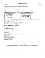
In certain cases where the impedance (inductance) of the CT is lower than the power available from the TR-1 &
TR-1P
a result indicating an “Over Current” error will be displayed.
Try testing with the lowest voltage setting.
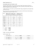
Tapped Secondary CT:
Current transformers with multiple secondary taps are easily tested. After each specific ratio is tested the H0 lead
can be moved to the next position and that ratio can then be tested.
*Please note: If testing CTs higher than a ratio of 100, use PT mode.


