


Raytech USA, Inc. All rights reserved
Ver. 1.13
11
THREE PHASE TRANSFORMER TESTING:
10
–
0
Ratio tests on three phase transformers are carried out on a single phase basis.
Understanding the configuration, phase relationship, and vector diagrams is required.
A detailed explanation and description of terminal markings, phase relationship, and vector diagrams is contained
in specification: C57.12.70 American National Standard Terminal Markings and Connections for Distribution and
Power Transformers.
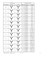
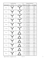
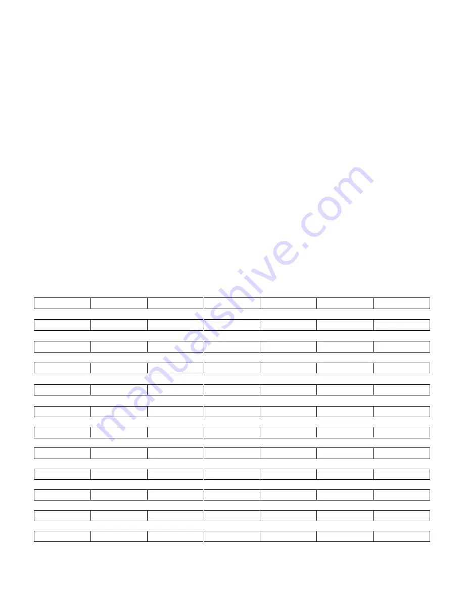
The tables on the following pages are guidelines for connecting and testing three phase transformers.
Table Key:
VECTOR GROUP:
The vector group column is the IEC vector group coding. The number indicates the phase displacement in
increments of 30
of the low side winding to the high side winding. For example a D-Y transformer with a Vector
group number of 3 would have a phase displacement of 3 x 30
or 90
. The low side winding has a lagging
displacement with respect to the high side winding.
PHASE:
The transformer phase that is being tested.
HV WINDING & LV WINDING:
The transformer connections that are selected for testing.
For example: D
– Y, phase “A” would require H1 & H3 to be tested again
st X1 & X2-X3
Note: (X2-X3 are jumpered together).
See charts on following pages:
PAGE 10
YN-yn 0
YN-yn 2
YN-yn 4
YN-yn 6
YN-yn 8
YN-yn 10
PAGE 10
YN-y 0
YN-y 2
YN-y 4
YN-y 6
YN-y 8
YN-y 10
PAGE 11
YN-zn 1
YN-zn 3
YN-zn 5
YN-zn 7
YN-zn 9
YN-zn 11
PAGE 11
YN-d 1
YN-d 3
YN-d 5
YN-d 7
YN-d 9
YN-d 11
PAGE 12
D-d 0
D-d 2
D-d 4
D-d 6
D-d 8
D-d 10
PAGE 12
D-yn 1
D-yn 3
D-yn 5
D-yn 7
D-yn 9
D-yn 11
PAGE 13
D-y 1
D-y 3
D-y 5
D-y 7
D-y 9
D-y 11
PAGE 13
D-zn 0
D-zn 2
D-zn 4
D-zn 6
D-zn 8
D-zn 10
PAGE 14
Y-yn 0
Y-yn 2
Y-yn 4
Y-yn 6
Y-yn 8
Y-yn 10
PAGE 14
Y-y 0
Y-y 2
Y-y 4
Y-y 6
Y-y 8
Y-y 10
PAGE 15
Y-zn 1
Y-zn 3
Y-zn 5
Y-zn 7
Y-zn 9
Y-zn 11
PAGE 15
Y-d 1
Y-d 3
Y-d 5
Y-d 7
Y-d 9
Y-d 11


