background image

Raytech USA, Inc.  All rights reserved

Ver. 1.13

8

TRANSFORMER TURNS RATIO TESTING

7

0

A Transformer Turns Ratiometer does exactly as its name implies; it is used primarily for checking how many
Turns of wire are in the primary side and the secondary side of a transformer. The Turns Ratio test set does not tell
exactly how many turns of wire are in the primary and secondary coils. But rather, it measures and displays the
Ratio of (or comparison of) the number turns in the primary coil to the number of turns in the secondary coil.

This is an extremely useful device for checking for shorted turns and incorrect settings of tap changers.

It is important to understand that the Nameplate Ratio on most transformers is the Voltage ratio (Voltage in:
Voltage out) and this Ratio is determined, basically, by the number of turns of wire on the Primary (High side), the
number of turns of wire on the Secondary (Low Side).

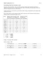
On a single phase Transformer the Turns Ratio is the same as the Voltage Ratio.

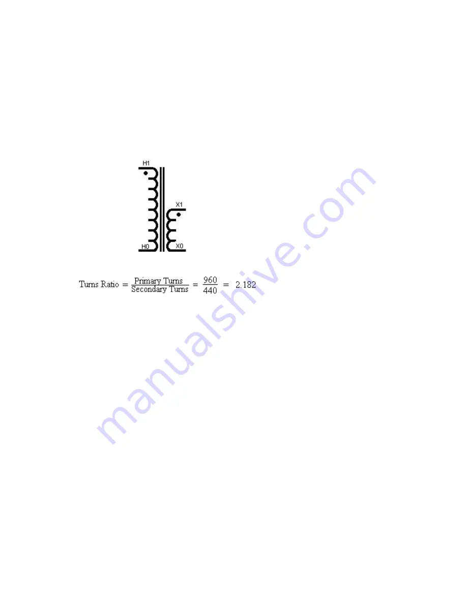
A Single Phase transformer:
For example:  The High Side Winding may contain 960 Turns : Low Side Winding 440 Turns.
Therefore:

Note: 3 Phase Transformers: Turns Ratio & Voltage Ratio are usually different.

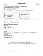
IMPORTANT NOTE 1: Hooking up to a transformer:

The TR-1 & TR-1P protect against improper hook-up to a transformer or testing a severely defective transformer.
Every effort has been made to alert the operator when something is wrong. The test system senses when it is
connected to a transformer, and in most cases, in a proper manner. The test system will not start a test unless it is
connected to a transformer.

Transformer Turns Ratiometer uses:

Transformer Turns Ratiometer is very useful as a tool for investigating problems associated with the core, the
windings, and the tap changer of transformers and the Raytech TR-1 can be used for:
1. Identify shorted turns and finding turn errors
2. Checking continuity of connections on a transformer
3. Locating defective and incorrect tap settings
4. Defining mislabeled terminals and nameplates

Turns Ratio testing is a required test during the manufacture of transformers. Turns Ratio testing should be a part of
a good routine preventative maintenance program as well as for acceptance testing.

Summary of Contents for TR-1

Page 1: ...S 2nd Street Perkasie PA 18944 USA Tel 888 4 THE SPY Tel 267 404 2676 Fax 267 404 2685 Single Phase Battery Operated Automatic Transformer Turns Ratiometer Test System Model TR 1 Model TR 1P Instruct...

Page 2: ...s 1 0 2 Uncrating Procedure 2 0 3 Introduction 3 0 4 Technical Specifications 4 0 5 Front Panel Description 5 0 6 Typical Display Screens 6 0 7 Transformer Ratio Testing 7 0 8 General Notes on Testing...

Page 3: ...s BEFORE APPLYING POWER Make sure the transformer to be tested is cleared and removed from operation GROUND THE INSTRUMENT To minimize shock hazard the instrument must be connected to a properly groun...

Page 4: ...rd TR 1P If any of the above items are missing or damaged please contact your local representative or Raytech USA Inc immediately RAYTECH USA Toll free service support telephone 1 888 4 THE SPY Note T...

Page 5: ...readings on site with laboratory precision The TR 1 TR 1P applies a preset test voltage on the HIGH winding side of the transformer and measures back through the LOW side of the transformer The result...

Page 6: ...Instruction Manual and instrument carry case with shoulder strap TR 1P includes paper refills for the panel mount printer TR 1 FEATURES Automatic measurements of Turns Ratio and Current Automatic det...

Page 7: ...inter allows the user to print out stored results or current results The single button on the printer is for Form Feed To tear paper pull paper towards the front of the instrument against the serrated...

Page 8: ...ge Selector Test Voltage Selector CT Mode Screen 40V selected Screen CT Auto selected License Screen Setup Screen Test in progress After test display Firmware is 0 85 Serial No is 272 100 Pre test scr...

Page 9: ...ormer For example The High Side Winding may contain 960 Turns Low Side Winding 440 Turns Therefore Note 3 Phase Transformers Turns Ratio Voltage Ratio are usually different IMPORTANT NOTE 1 Hooking up...

Page 10: ...ecked by connecting all of the measuring lead clips of the test set all together The GO Will appear in the test screen No Ratio test can be performed however Turn the system on by pressing the Rotary...

Page 11: ...gh the X leads The X leads must always have lower voltage than the H leads or an error will be displayed When testing Current transformers take care that the test leads are correctly attached In certa...

Page 12: ...or group number of 3 would have a phase displacement of 3 x 30 or 90 The low side winding has a lagging displacement with respect to the high side winding PHASE The transformer phase that is being tes...

Page 13: ...2 X0 A H1 H0 X0 X1 YN yn 6 B H2 H0 X0 X2 C H3 H0 X0 X3 A H1 H0 X2 X0 YN yn 8 B H2 H0 X3 X0 C H3 H0 X1 X0 A H1 H0 X0 X3 YN yn 10 B H2 H0 X0 X1 C H3 H0 X0 X2 A H1 H0 X1 X2X3 YN y 0 B H2 H0 X2 X1X3 C H3...

Page 14: ...H1 X0 X2 C H3 H2 X0 X3 A H1 H3 X2 X0 YN zn 7 B H2 H1 X3 X0 C H3 H2 X1 X0 A H1 H3 X0 X3 YN zn 9 B H2 H1 X0 X1 C H3 H2 X0 X2 A H1 H3 X1 X0 YN zn 11 B H2 H1 X2 X0 C H3 H2 X3 X0 A H1 H0 X1 X2 YN d 1 B H2...

Page 15: ...H1 X1 X3 C H3 H2 X2 X1 A H1 H3 X3 X1 D d 6 B H2 H1 X1 X2 C H3 H2 X2 X3 A H1 H3 X2 X1 D d 8 B H2 H1 X3 X2 C H3 H2 X1 X3 A H1 H3 X2 X3 D d 10 B H2 H1 X3 X1 C H3 H2 X1 X2 A H1 H3 X1 X0 D yn 1 B H2 H1 X2...

Page 16: ...X1X3 A H1 H3 X2X3 X1 D y 7 B H2 H1 X1X3 X2 C H3 H2 X1X2 X3 A H1 H3 X2 X1X3 D y 9 B H2 H1 X3 X1X2 C H3 H2 X1 X2X3 A H1 H3 X1X2 X3 D y 11 B H2 H1 X2X3 X1 C H3 H2 X1X3 X2 A H1 H2H3 X1 X0 D zn 0 B H2 H1H3...

Page 17: ...X0 X1 Y yn 6 B H2 H1H3 X0 X2 C H3 H1H2 X0 X3 A H1 H2H3 X2 X0 Y yn 8 B H2 H1H3 X3 X0 C H3 H1H2 X1 X0 A H1 H2H3 X0 X3 Y yn 10 B H2 H1H3 X0 X1 C H3 H1H2 X0 X2 A H1 H2H3 X1 X2X3 Y y 0 B H2 H1H3 X2 X1X3 C...

Page 18: ...2 X2 X0 A H1 H2H3 X0 X1 Y zn 7 B H2 H1H3 X0 X2 C H3 H1H2 X0 X3 A H1 H2H3 X2 X0 Y zn 9 B H2 H1H3 X3 X0 C H3 H1H2 X1 X0 A H1 H2H3 X0 X3 Y zn 11 B H2 H1H3 X0 X1 C H3 H1H2 X0 X2 A H1 H2H3 X1 X2 Y d 1 B H2...

Page 19: ...ement to use this calculation chart is that the connections to the transformer be made exactly as indicated in the previous charts See pages 10 to 15 Config Multiply reading With this factor to get Tu...

Page 20: ...sible causes for these messages 1 Faulty transformer under test 2 Low inductive low resistive loads such as windings without cores 3 Device under test was not properly demagnetized ERRATIC OR ERRONEOU...

Page 21: ...e responsibility of purchaser This warranty shall not apply to any accessories parts or materials not manufactured or supplied by RAYTECH USA Inc Equipment must be returned prepaid with a Return Mater...

Reviews: