Compass
STD 22
Installation and Service manual
Compass STD 22
Compass STD 22 Compact
13
Edition: Sept. 13, 2005
3646/110--233.DOC010302
1.1
CAN bus (CAN = Controller Area Network)
(CAN = Controller Area Network)
259.8
Gyro compass
Gyro compass
GPS compass
Operator unit
Distribution
unit
8 (12) x
heading
(course bus
or NMEA)
3 x step
1 x rate of turn
1x courseprinter
= terminating resistor
DV--bus
CAN bus
The CAN bus is a Multi-Master-Bus allowing the
connection of all devices and systems regardless
of their task and function. This means that any
number of devices can be connected. These de-
vices must be designed for CAN bus technology.
For the CAN bus it is essential that every bus user
is addressable via a unique address. This address
is set within each bus user.
The usable address range is from 01
(16)
to 3F
(16)
(address 00
(16)
is reserved for development pur-
poses).
Each bus user can send and receive data via the
CAN bus.
The CAN bus must be terminated at both ends via
an ohmic resistor (125 ohms). This terminating
resistor is activated by jumpers or switches (E10)
on the respective PCB.
There is a redundant bus system (CAN1 and
CAN2).
DV--bus:
Connections and settings for a DV--bus application
see manuals no.: 3647 “Distribution Unit” and
no.: 3648 “Operating Unit”.
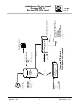
Figure1
:
Principle of CAN bus

