background image

Operator Unit

130--613

Operator Unit

11

Edition: March 11, 2005

3648/130--613.DOC010102

2.2.1.2

Changing the Default Settings

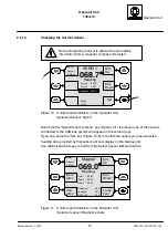
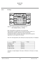
Below is a short description (shown at one example) how to change default values.

1

2

3

4

6

8

9

Up

Down

GYRO 1

068.7

°

Heading

Gyro 2

067.9

°

Gyro 3

068.1

°

Magnet 069.0

°

Man Speed:

Set

Select

Lat

10.0kn

Select

Speed

ESC

Figure 7:

Controls and Indicators on the Operator Unit

Changing the values:
The “Man Speed” function is called by pressing the “Select Speed” soft key (see
Figure 7/6) (as shown in Figure 7). The default value for this function is 10.0 kn. Press
the up or down keys (Figure 7/2 and 3) to increase or reduce this value by increments.
Confirm:
Once the value has been altered to a value within the permitted range, the two-colour
LED (Figure 7/8) flashes “yellow”. This means that the new value can be transferred to
the CAN bus. The new value is accepted when you press the “Set” key (Figure 7/4).
The amended value has been transferred successfully when the LED is no longer lit.
If the operation is not finalised, you can press the ESC key (Figure 7/1) to restore the
value you started with.
TIME OUT function:
If no key is pressed for a period of 12 seconds while starting altering a value, amend
mode is cancelled and the display reverts to the previous indication. To change the
value, you need to call the function again.

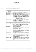
Summary of Contents for 130

Page 1: ...ax 49 4 31 30 19 501 Email Service raykiel com www raytheon anschuetz de 3648 130 613 DOC010102 Edition March 11 2005 Revision Sept 10 2005 Revision Nov 28 2005 Revision Jan 11 2006 Revision Feb 17 2006 Operator Unit Type 130 613 1 Description 2 Operation 3 Maintenance and repairs ...

Page 2: ...e liable to the payment of damages Toute communication ou reproduction de ce document toute exploitation ou communication de son contenu sont interdites sauf autorisation expresse Tout manquement à cette règle est illicite et expose son auteur au versement de dommages et intérêts Sin nuestra expresa autorización queda terminantemente prohibida la reproducción total o parcial de este documento así ...

Page 3: ...s 9 2 2 1 2 Changing the Default Settings 11 2 2 1 3 Adjusting Brightness and Contrast 12 2 2 1 4 Changing the Current Sensor 13 2 2 1 5 Menu selection 14 2 2 1 6 Lamp test 15 2 2 2 Alarm and Fault Handling 16 2 2 2 1 Alarm handling 16 2 2 2 2 Status and alarm messages an overview 18 2 2 2 3 General Error Messages 21 2 2 2 4 Warnings 24 3 Gyrocompass Operation 26 3 1 Selecting the Sensor 26 3 1 1 ...

Page 4: ...e 1 59 6 3 1 1 CAN bus adressees 60 6 3 1 2 Heading without correction values 61 6 3 1 3 Damping of the Rate of Turn 62 6 3 1 4 Speed Source 64 6 3 1 5 GPS Setup 65 6 3 2 Service Mode Page 2 66 6 3 2 1 DV bus application 67 6 3 2 2 Auto Heading Switch over 69 6 3 2 3 Deviation Table 72 6 3 2 4 Gyro Data 73 6 3 2 5 Software Versions 75 6 4 Switching Off the Operator Unit 77 7 Operator Unit maintena...

Page 5: ...tion November 28 2003 Appendix Operator Unit Dimensional Drawing 130 D 613 HP005 For operating in combination with a Satellite Compass STD 21 GPS see respective manual no 3717 Only for GGMR application All manually set values have to be set for both Distribution Units ...

Page 6: ...Operator Unit 130 613 IV Edition March 11 2005 3648 130 613 DOC010102 ...

Page 7: ...Operator Unit Operator Unit 130 613 V 3648 130 613 DOC010102 Edition March 11 2005 ...

Page 8: ...itioning System ESC Escape IP Internal Protectio kn Knots Lat Latitude LCD Liquid Crystal Display LED Light Emitting Diode Mag Magnetic Man Manual NMEA National Marine Electronic Association PCB Printed Circuit Board Pos Positon RoT Rate of Turn RS Recommended Standard Spd Speed VHW Velocity Heading through Water VTB Velocity below Water VTG Velocity through Ground ...

Page 9: ...gational system such as the gyro compass the GPS compass and the magnetic compass can be operated through the Operator Unit application described here Several Operator Units can be connected to a CAN bus There is no priority control system for connected Operator Units Each Operator Unit connected to the system has the same priority The Operator Unit is used to select use and monitor the navigation...

Page 10: ... PCBs The front panel contains the display 6 sealed membrane keys and a two colour LED The PCBs are connected to the display unit via an optical fibre An alarm transmitter is mounted behind the front panel to transmit audible alarms The Operator Unit is designed for two redundancy CAN CAN1 and CAN2 busses The Operator Unit is equipped with a PTC in the supply voltage line In the event of a fault s...

Page 11: ...ferent sensor or sub menu see also Figure 3 and section 2 2 1 4 Dim up Dim down GYRO 1 068 7 HEADING Aut Spd 08 5Kts Aut Lat 50 05 Gyro 2 067 9 Gyro 3 068 0 Magnet 069 0 Select Speed Select Sensor Menu Select Lat Contrast Lamp Test Figure 2 Example of a display after it has been put into operation Explanation of the controls and indicators The Operator Unit display is divided into the display sect...

Page 12: ...own Magnet 068 7 HEADING Gyro 1 067 9 Gyro 2 069 0 Gyro 3 068 9 Contrast Vari ation Select Sensor Menu Devi ation Deviation 03 0 Variation 04 0 Gyro Mag Diff 03 0 Lamp Test Figure 3 Example of the display when the Magnetic Sonde sensor is selected All equipment and sensors connected to the CAN bus take the data they require for their particular function from the CAN bus The selected sensor leads t...

Page 13: ...es can be connected These de vices must be designed for CAN bus technology For the CAN bus it is essential that every bus user is addressable via a unique address This address is set within each bus user The usable address range is from 01 16 to 3F 16 address 00 16 is reserved for development pur poses Each bus user can send and receive data via the CAN bus The CAN bus must be terminated at both e...

Page 14: ... 1 2 1 Mechanical data Length Width Height 80x192x96 Type of enclosure IP23 higher rating with special casing See also OPERATOR UNIT DIMENSIONAL DRAWING 130 D 613 HP005 1 2 2 Electrical data Supply voltage 24 V d c 9 36 V d c Current consumption 0 2A Interfaces 2 x CAN bus optional RS422 ...

Page 15: ...on the Operator Unit Figure 5 no Signification 5 1 5 2 5 3 5 4 5 5 5 6 Membrane keys The signification of the membrane keys is determined by Soft key fields 5 9 5 4 Red membrane key used to acknowledge alarms and confirm data entries Performing Lamp Test 5 7 LCD display 5 8 Two colour LED red alarm message yellow request to confirm where values have been changed a sensor has been selected Note If ...

Page 16: ... 4 1 2 the RS422 configuration is a special application only The Operator Unit switches on as soon as it has a supply of operating voltage Display once the operating voltage is present Dim up Dim down GYRO 1 068 7 Heading Aut Spd 08 5Kts Aut Lat 50 05 Gyro 2 067 9 Gyro 3 068 1 Magnet 069 0 Select Speed Select Lat Contrast Select Sensor Menu Lamp Test Figure 6 Display once the voltage supply is pre...

Page 17: ...laying of not selected sensors 2 Gyros and 1 Magnetic compass Gyro 1 067 9 Gyro 2 067 8 GPS 067 8 A maximum of 3 not selected sensors can be displayed Magnet selected Displaying of not selected sensors 2 Gyros and 1 GPS compass for operating the GPS with the Op erator Unit see manual no 3717 Gyro 2 067 9 GPS 067 8 Magnet 067 8 A maximum of 3 not selected sensors can be displayed Gyro 1 selected Di...

Page 18: ...or than heading information is not displayed 068 9 Q Quick Settling the heading value to which the gyro will settle is displayed 068 9 S Settling Stage the Gyro is still settling heading is displayed the precision is still restricted H Heating stage the activation of the quick settling function is not possible time to activate this function 3 minutes is over QS possib Quick Settling possible durin...

Page 19: ... Press the up or down keys Figure 7 2 and 3 to increase or reduce this value by increments Confirm Once the value has been altered to a value within the permitted range the two colour LED Figure 7 8 flashes yellow This means that the new value can be transferred to the CAN bus The new value is accepted when you press the Set key Figure 7 4 The amended value has been transferred successfully when t...

Page 20: ...Down key 2 to make it darker This setting is retained even after the equipment has been switched off To adjust the contrast first press the Dim Up 1 and Dim Down 2 keys simultaneously The display now changes 2 3 Contr Up Contr Down GYRO 1 068 7 Heading Gyro 2 067 9 Gyro 3 068 1 Magnet 069 0 Esc 1 Aut Spd 14 5Kts Aut Lat 46 05 Set Figure 9 Adjusting the contrast Once the display has changed see Fig...

Page 21: ...ime the Select Sensor Menu key Figure 10 1 is pressed one of the sensors connected to the CAN bus system will appear on the screen top If you now press the Set key Figure 10 2 to confirm the sensor you have selected heading data provided by that sensor will now display on the display unit Use the Exit and Set keys to exit from the Select Sensor Menu function Magnet 069 0 Gyro 1 068 7 Gyro 2 067 9 ...

Page 22: ...alarm horn may be adjusted and the actual software status is displayed Service see section 6 3 There are two pages which may be selected The pages contain Displaying of CAN bus addresses and heading without correction values as there are speed error correction and alignment error Adjustment of damping of the Rate of Turn Displaying and selection of speed source Activation of DV bus and adjustment ...

Page 23: ...p Test 1 Figure 12 Controls and Indicators on the Operator Unit By operating the softkey Lamp Test Figure 12 1 for appr 3 seconds the LED above this soft key lights up an acoustic alarm occurs with selected volume see section 6 2 and the brightness increases Dim Up Dim Down GYRO 1 068 7 Heading Gyro 2 067 9 Gyro 3 068 1 Magnet 069 0 Select Lat Select Speed Contrast Select Sensor Menu Aut Spd 14 5K...

Page 24: ...ontrols and Indicators on the Operator Unit alarm is indicated An alarm is indicated in two ways the two colour LED Figure 14 1 flashes red and the signal transmitter emits an audible signal The reason for and the origin of the alarm is also displayed In the event of an error the unselected sensors are flagged as not usable No audible signal is emitted Users cannot select a faulty sensor ...

Page 25: ...M 03 2 Present Alarms Gyro Mag Diff Figure 15 Controls and Indicators on the Operator Unit Example Difference threshold alarm is indicated After an alarm is acknowledged without a remedy the button Alarm Quit is replaced by the button Present Alarms the alphanumeric alarm message is no longer displayed only the LED red still lights up By pressing the button Present Alarms the alarm message is disp...

Page 26: ...sor fails Is displayed if the external connected speed sensor fails or generates unusable data and the operating mode Aut Speed is selected Pos Missing An external sensor fails Is displayed if the external connected position sensor fails or generates unusable data and the operating mode Aut Lat is selected Gyro Mag Diff Is displayed if the set heading difference threshold be tween a Gyro and a Mag...

Page 27: ...GPS Is displayed if the selected Gyro fails no further Gyro is connected and the automatic switch over function has switched to Gyro 3 GPS see also section 6 3 2 2 No Heading Blinking line below the heading line Is displayed together with Sensor Error Note The message Sensor Error is no longer displayed after acknowledging but the message No Heading still remains see also section 2 2 2 3 Heading H...

Page 28: ... 3 Com Data I F 4 Com Heading Failure Poor Sat signals Gyro Triad Error Accel Error These alarm messages are generated by the Satellite Compass STD 21 GPS These alarm messages are possible only if a Satellite Compass STD 21 is installed For detailed information see STD 21 manual no 3717 section troubleshooting PLEASE NOTE The red softkey Acknowledge alarm has to be pressed to display above mention...

Page 29: ...cond CAN bus No special message is output onto the display unit Once the data has changed over to the second bus data transfer will continue undisturbed User functions are not restricted as long as only one fault is present No usable data on the CAN bus Dim Up Dim Down GYRO 1 No Heading Gyro 2 Gyro 3 Magnet Select Speed Select Lat Select Sensor Menu Aut Spd Kts Aut Lat Figure 16 Controls and Indic...

Page 30: ...e error message stays on the display until the fault has been remedied After pressing the Alarm Ackn key the soft key Panel Setup is displayed too from software version E10 After operating this key Penel Setup the actual software version is displayed see also section 6 2 Both CAN bus plugs on the Operator Unit have come loose Magnetic Sonde selected First a Distribution Err is displayed than quit ...

Page 31: ...IT Contrast Figure 19 Controls and Indicators on the Operator Unit No CAN bus is connected to the Operator Unit 3 The display alters after 3 5 seconds and the error message NO CONNECTION is displayed see Figure 19 A visual and audible alarm is emitted Cause of this error message can be either a missing termination resistor a missing CAN bus connection or a wrong connected CAN bus Once the Alarm Ac...

Page 32: ... or more warnings These warnings do not stand for an error but they may lead to a defect if no measurement are attempt to eliminate the cause of this warnings For detailed information to warnings their possible causes and the respective measurements see Compass STD 22 manual There are 5 warnings possible each warning has a priority this priority is not displayed Warning Priority Voltage cut off Pr...

Page 33: ...dged operating the red push button the signal horn is on and the LED red blinks It is not necessary to acknowledge one of the other warnings Warnings and alarms may occur at the same time Alarms have to be handled prior acknowledged If the warning Voltage cut off an alarm occur at the same time the alarm has to be acknowledged first Dim Up Dim Down GYRO 1 068 7 Heading Magnet 069 0 Menu EXIT 2 Set...

Page 34: ...tors on the Operator Unit Gyro 1 sensor is selected Press the Select Sensor Menu soft key Figure 22 1 until the Gyro 2 line is selected Confirm the selection by pressing the Set Figure 22 2 softkey Heading information will now be output to the display by Gyro 2 see Figure 23 Dim Up Dim Down GYRO 2 067 9 Heading Gyro 1 068 7 Gyro 3 068 1 Magnet 069 0 Contrast Select Sensor Menu Select Speed Select ...

Page 35: ...n of the compass heading output from Gyro2 Select Sensor Menu Lamp Test Figure 24 Controls and Indicators on the Operator Unit Compass heading indication After Power ON Gyro1 is selected as the default compass and the heading value is displayed in large lettering All other available heading sensors are available for selection and are also indicated on the display for monitoring purposes They can b...

Page 36: ...e settling stage During the heating stage on the gyro system the heading information is not valid and the only indication is a set of dashes The Heating status is indicated flashing next to the heading indication With a second gyro system for example a H for heating is positioned alongside the monitor indicator see Figure 25 Dim Up Dim Down GYRO 1 Aut Spd 08 5kn Aut Lat 50 05 Gyro 2 H Gyro 3 H Mag...

Page 37: ...ision The gyro heading is indicated on the display during the settling stage The Settling status is indicated flashing next to the heading indication With a further gyro system a S for settling is positioned alongside the monitor display see Figure 26 Dim Up Dim Down GYRO 1 300 5 Aut Spd 08 5Kts Aut Lat 50 05 Contrast Select Speed Select Lat Heading Settling Select Sensor Menu Gyro 2 303 2 S Gyro ...

Page 38: ...Gyro 3 068 9 Magnet 069 0 Lamp Test Figure 27 Controls and Indicators on the Operator Unit Aut Spd selected In the event of a fault or if Aut Spd is not available you can switch over to Man Spd see Figure 28 The gyro uses the speed information to calculate the automatic speed error correction Dim Up Dim Down GYRO 2 067 9 Heading Contrast Select Speed Select Lat Select Sensor Menu Man Spd 10 2kn Gy...

Page 39: ...ing Select Speed Set 1 2 3 Aut Spd Gyro 1 068 7 Gyro 3 068 9 Magnet 069 0 10 2kn ESC Figure 29 Controls and Indicators on the Operator Unit after Aut Spd has been selected The key Figure 29 2 is now assigned with the Set function The LED Figure 29 3 flashes yellow Once confirmation is given via the Set key the changeover is make and the gyro system is corrected using the manually entered speed val...

Page 40: ...068 7 Gyro 3 068 9 Magnet 069 0 Figure 30 Controls and Indicators on the Operator Unit Man Spd selected Press the Select Speed key Figure 30 1 The cursor jumps to the manual speed indicator field and the value can be altered using the Up Figure 30 4 and Down Figure 30 5 keys Use the Set key Figure 30 2 to accept the value into the system and the flashing LED Figure 30 3 now goes out ...

Page 41: ...stem Since this is a non linear error the speed error table cannot take it into consideration The correction values are calculated within the gyro system and added or subtracted to the compass heading So in the event that the speed error correction function is actiavted by manually entering speed and latitude dynamic speed error correction will also be carried out This can lead to unexpected resul...

Page 42: ...rols and Indicators on the Operator Unit after Man Lat has been selected The key Figure 31 2 is now assigned with the Set function The LED Figure 31 3 flashes yellow Once confirmation is given via the Set key the changeover is made and the gyro system is corrected using the manually entered latitude values The changeover also affects the gyro system that is not currently selected GYRO 2 067 9 Head...

Page 43: ... Unit Man Lat selected Press the Select Lat key Figure 33 1 The cursor jumps to the manual latitude indicator field and the value can be altered using the Up Figure 33 4 and Down Figure 33 5 keys Use the Set key Figure 33 2 to accept the value into the system and the flashing LED Figure 33 3 now goes out Big differences of the latitude value which may occur while switching over from automatic to m...

Page 44: ...ng off and and on again of the compass Immediately after switching on of the compass it is possible to activate the Quick Settling function at the Operator Unit By this the heating stage and the settling stage are reduced to in total one hour After this time an usable heading information is displayed for the accuracy of the heading information see compass manual Time to activate this function is o...

Page 45: ...g stage no possibility for Quick Settling 3 minutes are over Figure 34 Controls and Indicators on the Operator Unit Heating stage of the selected gyro 1 Quick Settling is possible during a time of 3 minutes During this 3 minutes the menu line Menu has to be selected softkey Select Sensor Menu Dim Up Dim Down GYRO 1 Magnet 069 0 EXIT Gyro 2 H Gyro 3 H Contrast Select Speed Select Lat QS possible Se...

Page 46: ...of 3 minutes menu line Quick Settling selected Basic Menu Selected line Menu Display Menu Selected Quick Settling Dim Up Dim Down Quick Settling Set Select EXIT Gyro 1 Note Gyro 2 and gyro 3 not displayed because a Quick Settling is no longer possible Indication of H Heating stage means also Quick Settling no longer possible 3 minutes are over QS SET SET oper ated Figure 37 Controls and Indicators...

Page 47: ... Figure 37 After selection of Exit the basic menu is displayed Figure 38 Dim Up Dim Down GYRO 1 068 7 Magnet 069 0 Menu EXIT Gyro 2 H Gyro 3 H Contrast Select Speed Select Lat Qick Settling Select Sensor Menu Lamp Test blinking Figure 38 Controls and Indicators on the Operator Unit Function Quick Settling activated for gyro 1 This menu Quick Settling is displayed only if this function is possible ...

Page 48: ...gyro 2 status within 3 minutes after switching on gyro 3 is in the heating stage QS no longer possible Quick Settling is possible during a time of 3 minutes The procedure to activate the Quick Settling function corresponds to the procedure in section 3 4 1 Quick Settling activation of selected gyro Basic Menu Selected line Menu Display Menu Selected Quick Settling Dim Up Dim Down Quick Settling Se...

Page 49: ... the basic menu is displayed Figure 41 Dim Up Dim Down GYRO 1 068 7 Magnet 069 0 Menu EXIT Gyro 2 069 1 Q Gyro 3 H Contrast Select Speed Select Lat Heading Select Sensor Menu Lamp Test Figure 41 Controls and Indicators on the Operator Unit Gyro 1 in operation Gyro2 in Quick Settling Mode and Gyro 3 in the heating stage QS no longer possible 3 minutes are over This menu Quick Settling is displayed ...

Page 50: ...mpass is selected as the sensor providing the heading Vari ation Devi ation Magnet 069 0 Deviation 4 5 Variation 5 0 Diff G M 3 0 Dim Up Dim Down Select Sensor Heading Contrast Gyro 1 068 7 Gyro 3 068 9 Magnet 069 0 Lamp Test if the term Deviation is displayed in this field then the value of the deviation has to be entered according to section 4 1 1 as a single value Figure 42 Controls and Indicat...

Page 51: ...net is selected as heading sensor the magnetic heading value is monitored against the heading values from each Gyro for difference Dim Up Dim Down Magnet 069 0 Heading Set 1 2 Select Sensor Menu Gyro 1 068 7 Gyro 2 067 9 Gyro 3 068 9 Menu EXIT Figure 43 Controls and Indicators on the Operator Unit Menu line selected The menu line is selected by pressing the Select Sensor Menu key Figure 43 1 Enter...

Page 52: ...ure 45 1 and 2 the display Diff G M can also mean difference between GPS and magnet Confirm the values by pressing Set Leave the menu by selecting EXIT Up Down Magnet 069 0 Heading Set Select Menu Diff GG 03 0 Diff G M 03 0 EXIT 1 2 3 4 Figure 45 Controls and Indicators on the Operator Unit Diff G M 03 0 line selected The minimum threshold G M is 3 The maximum threshold G M is 89 9 Changeable in s...

Page 53: ...field Deviation If there is no therm Deviation in this field than the func tion of a deviation table is available this function reflect a higher development status At Distribution Unit with a lower development status the field has the therm Deviation In this case single correction value to each heading have to be entered according to section 4 1 1 1 At Distribution Unit with the function of a devi...

Page 54: ...ntrast Select Sensor Menu Deviation 4 5 Variation 5 0 Diff G M 3 0 1 Gyro 1 068 7 Gyro 3 068 9 Magnet 069 0 Figure 46 Controls and Indicators on the Operator Unit Magnetic compass selected Changing the Variation and Deviation using the Deviation Variation softkey Figure 46 The Change Deviation Variation menu Magnet 069 0 Heading 2 Esc Up Down 3 Set Deviation 4 55 Figure 47 Controls and Indicators ...

Page 55: ...re 47 2 or 3 Once you have confirmed using the Set key these values are accepted stored into an internal table and the magnet compass heading is corrected accordingly by interpolation of the set stored values The menu reverts back to its initial status Variation deviation in relation to location Select the variation input field by pressing the Variation key Figure 46 6 Change the value and finalis...

Page 56: ...key Set Select the line Service in the next display with soft key Select Sensor Menu and soft key Set Select the line Next page in the display Service Mode page1 with soft key Select Menu and soft key Set Select the line Deviation Table in the display Service Mode page2 with soft key Select Menu and soft key Set Up Down Deviation Tab Set Select Next Value Previ Value 000 009 010 019 020 029 030 03...

Page 57: ... be selected The soft keys Next value and Previ Value are enabled only if this function is reasonable respective term in the soft key is displayed for example no Next Value at the end of the deviation table With the soft keys Up and Down the correction value is adjusted and entered with the soft key Set the line Edit value and set value has to be selected with soft key Select With soft key Select ...

Page 58: ...eading Aut Spd 08 5kn Aut Lat 50 05 Gyro 2 067 9 GPS 068 8 Magnet 069 0 Select Speed Select Lat Contrast Select Sensor Menu Lamp Test Figure 50 Controls and Indicators on the Operator Unit Display with a GPS in the application Dim up Dim down GPS 068 7 Heading Gyro 1 067 9 Gyro 2 068 8 Magnet 069 0 GPS Config GPS Hdg Contrast Select Sensor Menu Lamp Test Lat 054 21 712 N Lon 010 08 434 E Figure 51...

Page 59: ... deviation more than the adjusted threshold than there will be a difference alarm displayed and output A conclusion about which of the connected sensors deviates is not possible Each connected sensor has to be checked depending his function All adjustments necessary for a difference alarm are shown in the table below Parameter G M G G Minimum threshold 3 1 Maximum threshold 89 9 89 9 Increment 1 1...

Page 60: ...o Gyro 3 and Comparison Gyro 2 to Gyro 3 Gyro 2 selected Comparison Gyro 2 to Gyro 1 and to Gyro 3 and Comparison Gyro 1 to Gyro 3 Gyro 3 selected Comparison Gyro 3 to Gyro 1 and to Gyro 2 and Comparison Gyro 1 to Gyro 2 Gyro 1 Gyro 2 Gyro 3 Magnetic compass Gyro 1 selected Comparison Gyro 1 to Gyro 2 and to Gyro 3 and Comparison Gyro 2 to Gyro 3 and Comparison Gyro 1 to Magnetic compass Gyro 2 se...

Page 61: ...o 1 to Gyro 2 and to GPS and Comparison Gyro 2 to GPS Gyro 2 selected Comparison Gyro 2 to Gyro 1 and to GPS and Comparison Gyro 1 to GPS GPS selected Comparison GPS to Gyro 1 and to Gyro 2 and Comparison Gyro 1 to Gyro 2 Gyro 1 Gyro 2 GPS Magnetic compass Gyro 1 selected Comparison Gyro 1 to Gyro 2 and to GPS and Comparison Gyro 2 to GPS and Comparison Gyro 1 to Magnetic compass Gyro 2 selected C...

Page 62: ...reshold Only one level threshold for all connected gyros can be set and adjusted The Satellite Compass STD 21 GPS is handled as a Gyro Dim Up Dim Down Magnet 069 0 Heading Set 1 2 Select Sensor Menu Gyro 1 068 7 Gyro 2 067 9 Gyro 3 067 9 EXIT Menu Figure 52 Controls and Indicators on the Operator Unit Diff Alarm line selected The menu line is selected by pressing the Select Sensor Menu key Figure ...

Page 63: ...u can select Diff G G 03 0 on the Diff Alarm sub menu by pressing Set Figure 54 2 LED Figure 54 3 flashing and then alter it by pressing Up Down Figure 54 4 and 5 Confirm the value by pressing Set LED Figure 54 3 no longer flashes Leave the menu by selecting EXIT Up Down Magnet 069 0 Heading Set Select Menu Diff G G 03 0 Diff G M 03 0 EXIT 2 3 4 5 G can be a Gyro or a GPS Figure 54 Controls and In...

Page 64: ...trols and Indicators on the Operator Unit Menu selected The menu line is selected by pressing the Select Sensor Menu key Figure 55 1 Enter the menu by pressing Set Figure 55 2 and a sub menu is displayed Dim Up Dim Down GYRO 1 069 0 Heading Set 1 2 Select Menu Diff Alarm Panel Setup Service EXIT Figure 56 Controls and Indicators on the Operator Unit sub menu Panel Setup selected The sub menu line ...

Page 65: ...me 1 means lowest adjustment By operating softkey Test Horn Figure 57 4 the adjusted volume can be tested Information about the software version is displayed only With Select to the Exit line and with Set this function can be closed PLEASE NOTE A display without any heading information for example a m display will be displayed for at least appr 10 seconds if there are no activities After these 10 ...

Page 66: ...Next Page Back Exit Depends on the development status If a sub menu is not displayed it cannot be selected Only if a Satellite Compass STD 21 GPS is connected In the sub menu Service Mode it is possible to adjust values and read out information for service purpose only Dim Up Dim Down GYRO 1 069 0 Heading Set 1 2 Select Sensor Menu Gyro 2 068 7 Gyro 3 067 9 Magnet 067 9 EXIT Menu Figure 58 Control...

Page 67: ... Figure 59 Controls and Indicators on the Operator Unit Service page 1 menu selected Each service function has a time out counter of 60 seconds If there are no activities within this time the display changes to a display with heading information By selection of the respective menu line and with the key Set the selected menu is displayed By selecting the menu line Next page the page two of the serv...

Page 68: ... this function Basic menu select Menu line select Service line select function CAN Devices Dim Up Dim Down CAN Devices Set 01 OPU 03 OPU 10 GPS 12 GY1 13 GY2 20 DU 21 DU Exit Service Timeout in 52 s Figure 60 Controls and Indicators on the Operator Unit Function CAN Devices OPU Operator Unit GY1 Gyrocompass1 DU Distribution Unit GPS Satellite Compass STD21 GPS With this function all addressees wit...

Page 69: ...tion alignment error are displayed Inputs and or changes are not possible in with this function Basic menu select Menu line select Service line select function Heading uncorr Dim Up Dim Down Heading unc Set Gyro 1 205 1 Gyro 2 205 8 Gyro 3 205 6 Magnet 204 9 Exit Service Timeout in 57 s Figure 61 Controls and Indicators on the Operator Unit Function Heading uncorr With Select to the Exit line and ...

Page 70: ... in the Distribution Unit type 138 118 Basic menu select Menu line select Service line select function Rate of Turn Dim Up Dim Down ROT Min Set 1 2 Gyro1 001 0 Gyro2 000 3 Mag 007 0 Rate Gyro 004 4 Damp 0 Damp 1 selected Damp 2 Exit Service Timeout in 55 s Select Figure 62 Controls and Indicators on the Operator Unit Function Rate of Turn With this function the Rate of Turn of selected heading sen...

Page 71: ...Turn of an external Rate of Turn sensor connected at the Distribution Unit This line is not shown if there is no Rate of Turn sensor connected Damp 0 means strong damping Damp 1 means middle damping Damp 2 means small damping With Select to the Exit line and with Set this function can be closed If there is no Rate of Turn indicator connected in the respective application the RoT displays for STD21...

Page 72: ...s if no external speed sensor is con nected Basic menu select Menu line select Service line select function Speed Source Dim Up Dim Down Speed Source Set Puls Log selected VHW available VTG available VBW Wtr not available VBW Gnd not available Exit Service Timeout in 55 s Select Figure 63 Controls and Indicators on the Operator Unit Function Speed Source selected Default adjustment is Puls Log Oth...

Page 73: ... 1 5 GPS Setup Dim up Dim down GPS Setup Serial Port 3 Serial Port 4 PU Mounting AU Alignment GPS Pos Select Set Sat Status Software Versions Figure 64 Controls and Indicators on the Operator Unit GPS Setup selected With this service menu it is possible to Display software versions of Processor Unit GPS and Operator Unit Adjust the data format for the serial outputs 3 and 4 Adjust position and loc...

Page 74: ...Operator Unit Service page 1 menu selected With Select Menu to menu line Next Page and soft key Set the second page of the service mode is displayed see Figure 66 Dim Up Dim Down Service page 2 Set 1 2 Select Menu Auto Heading DV Bus Deviation Table Gyro Data Software Versions Back Exit Figure 66 Controls and Indicator on the Operator Unit Service page 2 menu selected With Back the page 1 of servi...

Page 75: ...nu select Menu line select Service line select DV Bus line The selection of this line DV bus is only possible if the distribution unit is equipped with this feature Older versions of the distribution unit do not have this feature in this case the line DV bus is not displayed Select Service line select DV Bus line select function DV Bus Yes No DV Bus DV Bus Y Address 014 Set Values Exit Service Tim...

Page 76: ...e in the DV bus application Up Down DV Bus DV Bus Y Address 014 Set Values Exit Service Timeout in 55 s Select 1 2 Figure 68 Controls and Indicators on the Operator Unit Function DV Bus address selected Select DV Bus line select function Set Values Up Down DV Bus DV Bus Y Address 014 Set Values Exit Service Timeout in 55 s Select 1 2 Set Figure 69 Controls and Indicators on the Operator Unit Funct...

Page 77: ...n takes place It is to select if a change over to the next Gyro GPS or to a Magnetic compass should be performed An automatically switching back is not possible A switching back has to be performed manual see also section 3 1 With Select Menu select the function Auto Heading and quit with Set Dim Up Dim Down Service page 2 Set Select Menu DV Bus Back Exit Auto Heading Figure 70 Controls and Indica...

Page 78: ...o Gyro GPS Y to TMC N Set Values Back Exit Service Timeout in 50s Without GPS With GPS Figure 71 Controls and Indicators on the Operator Unit Function Auto Heading Only if a Satellite Compass STD 21 GPS is integrated in this application the GPS is displayed The following table shows the automatically switch over from a defect but selected sensor to the next possible sensor ...

Page 79: ...Gy 2 Gyro 2 Switched to Gy 2 Gyro 1 Switched to Mag TMC Switched to Mag Gyro 1 Gyro 2 Switched to Gy 2 Gyro 2 TMC Switched to Mag Gyro 1 Gyro 2 Switched to Gy 2 Switched to GPS GPS TMC Switched to GPS Switched to Mag Gyro 1 GPS Switched to GPS GPS TMC Switched to Mag GPS Switched to Mag TMC Switched to Mag Gyro 2 Switched to Gy 1 Gyro 1 Switched to Gy 1 ...

Page 80: ...ss or a second gyro a GPS connected to the compass system If one or both possibilities to switch over are selected with N so the respective automatic switch over function is not enabled and it has to be switched over manually at the Operator Unit Only if an automatic switch over to a gyro GPS or a Magnetic compass took place a message like Switched to Gy1 Switched to Gy2 Switched to Gy3 Switched t...

Page 81: ... 213mA mA Pump Supply 22 7V V Pump Current 155mA mA Sensor PCB OK Power PCB OK Gyro PCB OK Connect PCB OK Set Service Timeout to 120s Exit Service Timeout in xxxs Figure 72 Controls and Indicators on the Operator Unit Sub menu Gyro Data selected Two Gyros connected one with an older development status Parameter Meaning Gy1 15 Gyro 1 with Can bus address 15 Temperature Temperature of the supporting...

Page 82: ...120s or Exit can be selected By operating the softkey Set and selected line Set Service Time out to 120s the internal counter is set to 120 seconds again The standard menu Figure 2 is displayed if this internal counter counts to zero By operating softkey Set and selected line Exit the display Service mode page1 is displayed again ...

Page 83: ...th an older development status Figure 73 Controls and Indicators on the Operator Unit Submenu SW Versions displayed One Gyro and one Distribution Unit connected Display Meaning Gy1 15 Gyro 1 with CAN bus address 15 110 233 P01 E10 00 110 233 Compass STD 22 P01 Program at the Sensor PCB P02 Program at the Power PCB P03 Program for MC 1 at the Outer Sphere PCB P04 Program for MC 1 at the Outer Spher...

Page 84: ...120s or Exit can be selected By operating the softkey Set and selected line Set Service Time out to 120s the internal counter is set to 120 seconds again The standard menu Figure 2 is displayed if this internal counter counts to zero By operating softkey Set and selected line Exit the display Service mode page1 is displayed again ...

Page 85: ...2 6 4 Switching Off the Operator Unit The equipment is switched off when the voltage supply to the operator unit is switched off Even if the equipment in question is installed as the end device on a CAN bus application the operation of the other connected devices will not be affected ...

Page 86: ...complete Operation during a replacement can only be performed when the CAN bus is terminated It is absolute necessary that the CAN bus is terminated correctly on both ends If there is no terminator by jumpers or switches within the respective devices than each CAN bus CAN1 and CAN2 has to be terminated by in total 2 resistors each 120Ohm from CAN low to CAN high PLEASE NOTE There are no changes re...

Page 87: ...r Unit rear view with casing removed 1 Hexadecimal switch B24 0 to F for setting the device address 2 Hexadecimal switch B23 0 to F for setting the device address 3 Plug B1 either CAN 1 or RS422 Transmit depending on jumper 4 Plug B2 either CAN 2 or RS422 Receive depending on jumper 5 Jumper B14 CAN 2 RS 422 Receive 6 Jumper B15 CAN 2 RS 422 Receive 7 Jumper B13 plugged CAN1 Bus terminating resist...

Page 88: ...d be installed Below mentioned table shows the agreements depending on the device addresses within a navigation system Device s CAN Bus Ad dress decimal CAN Bus Ad dress hexadecimal Operator Units 01 to 09 01 to 09 GPS 10 to 13 0A to 0D Sensors Gyro Compass 14 to 19 0E to 13 Distribution Units 20 to 29 14 to 1C Repeaters 30 to 1E to The device address can be allocated within a CAN bus system only ...

Page 89: ...erator Unit 81 Edition March 11 2005 3648 130 613 DOC010102 Hexadecimal switch B24 switch position 0 to F always set to 0 for the Operator Unit Hexadecimal switch B23 switch position 1 to 9 Figure 75 Setting the device address ...

Page 90: ... In order to ensure that the compass operates correctly it is essential that you follow the procedures described below for establishing cable connections Cable type CAN bus and RS422 interface manufacturer s recommendation 6x0 75mm2 twisted with screening Cable type voltage supply Raytheon cable no WN219 401 3 0 with connected plug or 3x0 75mm2 twisted Strip approx 180 mm of the cable length Make ...

Page 91: ... Edition March 11 2005 3648 130 613 DOC010102 Connect the plug as shown in Figure 78 or Figure 79 Plug the plug into the corresponding counter plug Figure 77 Example of a CAN1 bus CAN2 bus connection the Operator Unit is not the end device ...

Page 92: ... 2 CAN high 3 GND 1 CAN low 2 CAN high 3 GND Connection to supply voltage Cable no WN219 401 3 0 CAN1 or CAN 2 connection to the plug Operator Unit CAN Bus connection with terminating resistor Jumper B13 and Jumper B16 see section 8 4 1 2 CAN1 high CAN1 low Connector pin assignment White 9V to 36V DC Brown 0V Black Screen B1 B2 GND CAN2 high CAN2 low GND Figure 78 Making the connections to the plu...

Page 93: ... 2 3 Pin 1 2 3 Plug B1 RS422 Transmit Plug B2 RS422 Receive 1 TX 2 TX 3 GND 1 RX 2 RX 3 GND RS422 connection Plug B1 Transmit Plug B2 Receive GND RS 422 TX RS 422 TX GND RS 422 RX RS 422 RX OPTION currently not used Figure 79 Making the connections to the plugs for RS422 interface TX and RX ...

Page 94: ...Plugging in the jumpers Jumper Pin 3 2 1 Default Function B11 Default Plug B1 CAN 1 Plug B1 RS422 B12 Default Plug B1 CAN 1 Plug B1 RS422 B13 CAN bus terminating re sistor plugged in on end device only B14 Default Plug B1 CAN 2 Plug B1 RS422 B15 Default Plug B1 CAN 2 Plug B1 RS422 B16 CAN bus terminating resistor plugged in on end device only ...

Page 95: ......

Reviews:

Related manuals for 130