Operator Unit
130--613
Operator Unit
79
Edition: March 11, 2005
3648/130--613.DOC010102
8
Installation
8.1
Assembly
The Operator Unit must be assembled with the aid of dimensional drawing
130--613 HP005 either on an angled fixing bracket or desk-flush mounted.
Make sure that the installation is resistant to sea-water.
8.2
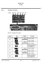
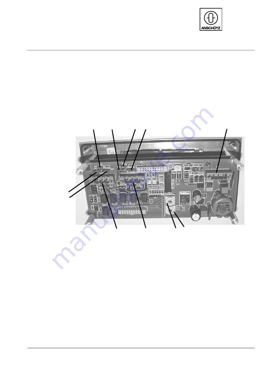
Overview of switches, jumpers and plugs
1
2
3
4
5
6
7
8
9
10
11
Figure 74: Operator Unit, rear view (with casing removed)
1
Hexadecimal switch B24 (0 to F) for setting the device address
2
Hexadecimal switch B23 (0 to F) for setting the device address
3
Plug B1, either CAN 1 or RS422 Transmit (depending on jumper)
4
Plug B2, either CAN 2 or RS422 Receive (depending on jumper)
5
Jumper B14, CAN 2 -- RS 422 (Receive)
6
Jumper B15, CAN 2 -- RS 422 (Receive)
7
Jumper B13 (plugged -- CAN1 Bus terminating resistor on end device only)
8
Jumper B12, CAN 1 -- RS 422 (Transmit)
9
Jumper B16 (plugged -- CAN2 Bus terminating resistor on end device only)
10
Jumper B11, CAN 1 -- RS 422 (Transmit)
11
Plug B7, voltage supply (9--36 V d.c.)


