Installation and Service manual
Compass STD 22
74
Edition: May 20, 2005
3646/110--233.DOC010302
3.1.1
General information concerning installation of the STD 22 Compass
When fitting components, observe the following spacing:
Fit the compass enclosure so that the display can be viewed from above and the cover
of the enclosure can be removed (see also Dimensional Drawing 110--133.HP005).
To ensure fault-free operation of the STD 22 Compass, it is essential to follow these
directions, safety notes and installation instructions.
Instructions relating to cable cross-sections and earth connections must be adhered to.
The tools which are specified for installing the compass must be used.
Only original parts or parts approved by the manufacturer may be used in connection
with the STD 22 Compass.
See also Cable Connection Diagram 110--233 HP009 or HP0029 for the STD 22
Compass.
Gyro Compass should not be installed in oil--containing ambient air, within surrounding in
vibration and should installed on a vibration--free platform.
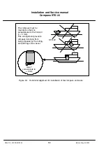
Gyro compass should be installed on the ships‘ line (vertical and horizontal).
The installation of the power supply (AC/DC--Converter) should only be per-
formed by an experienced electrician.
The 24VDC supply voltage should be engineered as a low--
security--voltage according to SELV.
In some system configurations it is necessary to take off heading
information from the compass direct -- additional to the heading
information on the CAN bus. This heading information is
uncorrected (without SEC)!
Corrected heading information (with SEC) can be taken off in these
system configurations from the distribution unit only.

