background image

04.09.08

Ludzuweit

23.09.08

Summary of Contents for 133-560 NG011

Page 1: ...stfach 1166 D 24100 Kiel Germany Tel 49 4 31 30 19 0 Fax 49 4 31 30 19 840 Email Service raykiel com www raytheon anschuetz com 3969 DOC010102 Edition August 2014 Repeater Compass Type 133 560 NG011 t...

Page 2: ...attet Zuwiderhandlungen verpflichten zu Schadenersatz nderungen dieses Dokuments und dessen Inhalt bleiben vorbehalten This document and its content are copyright protected Distribution reproduction a...

Page 3: ...REPEATER COMPASS TYPE 133 560 2 1 2 1 Structure of operation and configuration 2 1 2 2 Indications 2 2 2 2 1 Analogue heading indication 2 2 2 2 2 Digital heading display 2 3 2 2 3 Heading source indi...

Page 4: ...5 DISPOSAL 5 1 Table of Figures Figure 1 1 View of the front panel of the Repeater Compass 1 1 Figure 1 2 Operating and indicating elements on the front panel of the Repeater Compass 1 2 Figure 2 1 T...

Page 5: ...that the gyro compass has settled before using its heading data Warning Always check the plausibility of the indicated heading against other heading sources navigational aids Warning Mechanical or el...

Page 6: ...ue from a satellite compass G GYRO Gyro compass HCHDM NMEA telegram Heading Magnetic HCHDT NMEA telegram Heading True from a magnetic compass HDT NMEA telegram Heading True HP Auxiliary paper HilfsPap...

Page 7: ...____________________________________________________________________ Edition August 2014 V 3969 DOC010102 Repeater Compass 133 560 Change History Date Change May 30 2013 New edition July 01 2014 Updat...

Page 8: ...________________________________________________________________________________________________________________ 3969 DOC010102 VI Edition August 2014 Repeater Compass 133 560 Intentionally left blank...

Page 9: ...THDs via a serial interface Course BUS NMEA or a CAN Bus It can be configured to indicate the selected heading from a heading management system or INS or to indicate one heading source gyro satellite...

Page 10: ...f the front plate on the left side refer to Figure 1 2 a LED can light up in one of three colours red yellow green and shows alarm red proper function green or restricted function yellow Below the LED...

Page 11: ...s 133 560 1 2 2 Principle of operation The Repeater Compass receives the heading information from a gyro compass from a magnetic compass or from a satellite compass by means of serial heading transmis...

Page 12: ...102 1 4 Edition August 2014 Repeater Compass 133 560 1 2 3 Function key overview Comments notes Normal operation Dim mode see sections 2 5 to 2 7 Test and actual configuration status see section 2 7 3...

Page 13: ...elf Please note If the Repeater Compass is configured as CAN Bus Repeater the external central dimming is capable in both directions 2 Function TEST see section 2 7 3 This function is activated by ope...

Page 14: ...ddress mode is activated by operating the key for approx five seconds into max brightness direction after the configuration display is shown 5 Function CORRECTION of the Analogue Indications Cards see...

Page 15: ...for flush mounting standard IP23 56 2 133 560 NG013 133 560 HP028 Repeater Compass for bulkhead mounting IP44 3 133 560 NG014 133 560 HP030 Repeater Compass for wall mounting IP44 4 133 560 NG015 133...

Page 16: ..._______________________________________________________________________________________________________________ 3969 DOC010102 1 8 Edition August 2014 Repeater Compass 133 560 Intentionally left blank...

Page 17: ...NMEA Normal operation Test and show adjusted configuration Test Software status Selected interface Selected heading source Selected heading indication offset selected serial interface Baud rate Numbe...

Page 18: ...lected heading indication offset selected serial interface CAN Bus address Normal operation Configuration Serial interface CAN Bus CAN Bus address No heading offset Heading offset Correction of analog...

Page 19: ...o equipped with a digital heading display on the left side of the front panel 2 2 3 Heading source indication Additional there is a heading source indication Three line indicator at a top right positi...

Page 20: ...lizes the status or alarm of the Repeater Compass and of the telegram Table 2 1 LED signalling No LED NMEA interface CAN Heading Serial interface 1 green Repeater Compass is available and the telegram...

Page 21: ...Notes on the operating instructions Follow step by step the operating procedure shown in the corresponding sections If necessary helpful information in short form has been added to the figurative repr...

Page 22: ...he heading sensor source is indicated by a three line display at the top right of the front plate If the Repeater Compass is switched on and there is no interface connected the messages below are indi...

Page 23: ...ndication at the Repeater Compass After the heating stage has ended the settling stage of the gyro compass starts This is indicated by a yellow LED During this settling stage the heading is indicated...

Page 24: ...heading information is shown with a 3 line display at the top right of the front plate The heading source light up green Gyro Mag or Sat Indications Comments notes Valid heading from the gyro magneti...

Page 25: ...the display illumination 3 line display Status LED Function key With the first operation of the key the brightness will increase After a short release of the key and operating it again the brightness...

Page 26: ...aytheon Ansch tz supply the brightness is adjusted according to the brightness percentage of the telegram 2 7 2 2 Central Dimming via CAN Bus If connected to CAN Bus the Repeater Compass can also be c...

Page 27: ...al Operation NMEA or course bus Indications Comments notes Operate key1x Software status shown example only Operate key2x Selected interface type SCI Serial controlled interface as shown Do not operat...

Page 28: ...this heading source is for direct gyro compass connection only Operate key4x Heading indication 000 for normal operation as shown 180 turned by 180 e g for ferries Operate key5x Type of serial interf...

Page 29: ...tic or satellite compass Standard configuration if connected to CAN Bus Operate key4x Heading indication no offset Operate key5x CAN Bus address Possible CAN Bus addresses 30 63 Please note If more th...

Page 30: ...ed parameter can be activated by holding the key operated until the parameter blinks Multiple selections of parameters are possible Caution Switch off the power supply of the Repeater Compass after fi...

Page 31: ...e of interface Please note The change of the CAN Bus interface type is effected only after switching off and on again after completion of the configuration Operate key2x CAn_ CAN Bus interface CAN Bus...

Page 32: ...his case not satellite compass Operate key4x G_M_ Heading can be transmitted from a gyro magnetic or satellite compass Operating with NMEA only one telegram must be activated Operate key5x G_ _ Headin...

Page 33: ...Heading transmitted from a satellite compass Operate key13x CHdT Magnetic compass telegram HCHDT heading magnetic Heading transmitted from a magnetic compass heading corrected Operate key14x CHdG Magn...

Page 34: ...d Please note The change of the CAN Bus interface type is effected only after switching off and on again after completion of the configuration Operate key3x Next CAN Bus address Operate key4x Enter ad...

Page 35: ...magnetic compass is selected There will be no heading indication CHDT Heading transmitted from magnetic compass but Gyro or Satellite compass is selected There will be no heading indication HdG Headi...

Page 36: ...igured if the dimming should follow the DDC telegram or not factory setting Dimming Group 0 This can be done via the Configuration Tool AS The following steps are required Connect the Repeater Compass...

Page 37: ...equired to connect the Repeater Compass via the CAN Bus Distribution Unit AS Drawing Number 138 128 to the redundant CAN Bus of the Standard 22 System Please follow the following steps for configurati...

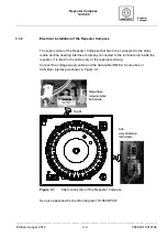
Page 38: ...supply Indications Comments notes yellow green e g this line indicates that the lubber line sensor has detected the zero position Operate the key for approx 16 seconds until is displayed the display i...

Page 39: ...ading of the ship Measures Check connections or call RAYTHEON Ansch tz service Indications Comments notes LED lights up red continuously and cannot be dimmed to zero Types of errors Serial interface d...

Page 40: ..._______________________________________________________________________________________________________________ 3969 DOC010102 2 24 Edition August 2014 Repeater Compass 133 560 Intentionally left blan...

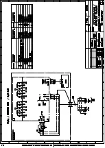
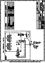
Page 41: ...connection the supply voltage must be switched off Ensure that the supply voltage cannot be switched on during installation Please note The Repeater Compass should be connected at the cable ends witho...

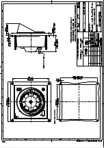
Page 42: ...sk flush mounting bulkhead mounting wall mounting For mounting the Repeater Compass pay attention to the following The cards the operating and indicating elements should be well addressable Protect th...

Page 43: ...has to be connected to the ships mains and the heading interface is already connected to the terminal strip inside the repeater It is fixed in the cable entry of the repeaters casing Connect the volta...

Page 44: ...B1 1 supply voltage B1 2 supply voltage B1 3 GND supply voltage B5 1 CAN High or Rx B5 2 CAN LOW or Rx B5 3 CAN GND CAN Bus is automatically terminated after selection configuration as the serial int...

Page 45: ...indication cards has to be checked frequently The indication has to correspond to the digital indication If the indications differ switch off the supply voltage and restart the Repeater Compass If the...

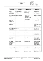
Page 46: ...ss Serial interface defective or transmitted telegram invalid Heading sensor transmits no or invalid data Check the heading source sensor False configuration of the Repeater Compass Configure Repeater...

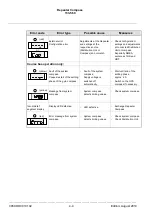
Page 47: ...r line or keep moving Disturbed calibration Restart Repeater Compass Off On several times if needed Exchange Repeater Compass if necessary Heading indication frozen constant External error Disturbed o...

Page 48: ...or compass Especially NMEA sentences THS and HDT Course bus operation only Fault of the system compass Causes restart of the settling phase of the gyro compass Fault of the system compass Supply volta...

Page 49: ...__________ Edition August 2014 5 1 3969 DOC010102 Repeater Compass 133 560 5 Disposal The DC DC Converter or components of it can be disposed according to the respective national regulations for elect...

Page 50: ..._______________________________________________________________________________________________________________ 3969 DOC010102 5 2 Edition August 2014 Repeater Compass 133 560 Intentionally left blank...

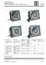
Page 51: ...003322 D2865 3 Tochterkompass basaltgrau RAL 7012 IP 44 Repeater Compass basalt grey RAL 7012 IP 44 133 560 NG014 4003338 D2865 4 Tochterkompass basaltgrau RAL 7012 IP 56 Repeater Compass basalt grey...

Page 52: ......

Page 53: ...19 08 10...

Page 54: ...04 09 08 Ludzuweit 23 09 08...

Page 55: ...04 09 08 Ludzuweit 23 09 08...

Page 56: ...04 09 08 Ludzuweit 23 09 08...

Page 57: ...04 09 08 Ludzuweit 23 09 08...

Page 58: ...04 09 08 Ludzuweit 23 09 08...

Page 59: ......

Page 60: ...04 09 08 Ludzuweit 23 09 08...

Page 61: ...04 09 08 Ludzuweit 23 09 08...

Page 62: ...04 09 08 Ludzuweit 23 09 08...

Page 63: ......

Reviews:

Related manuals for 133-560 NG011