OPERATION
AUTOPILOT
NautoPilot 5000 Series
47
4002.DOC010102
Edition: September 2014
2
Operation
2.1
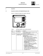
Operation elements at the NautoPilot Operator Unit
Figure 20: NautoPilot Operator Unit (operation elements)
1
2
3
4
5
6
7
8
NautoPilot 5000 Series
Table 3
NautoPilot Operator Unit (operation elements)
Pos.
Designation
Remarks
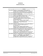
Figure 20/1
Touchscreen
For the display of data and operation of the
Autopilot via soft--keys.
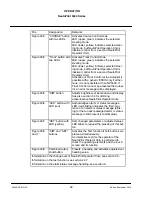
Figure 20/2
”HEADING” button
with two LEDs
Activates Heading Control mode.
LED (upper, green) indicates the selected
steering mode.
LED (lower, yellow) indicates:
-- Selected steering mode, but NautoPilot
Operation Unit is inactive (control from a
second NautoPilot Operator Unit).
The inactive NautoPilot operator Unit
serves as a display only (”OU Display” is
displayed at the top right corner).
--
AS application:
“Standby” is displayed at the top right
corner, the Autopilot can be activated by
pressing the button “Heading”.
--
Standalone application:
Autopilot cannot be activated.
A switching over of the Main Steering
Switch to “AUTO” the lower LED is off and
the upper LED is alight (steering mode is
“Heading Control”.

