OPERATION
NautoPilot 5000 Series
48
4002.DOC010102
Edition: September 2014
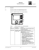
Pos.
Designation
Remarks
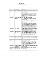
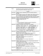
Figure 20/3
”COURSE” button
with two LEDs
Activates Course Control mode.
LED (upper, green) indicates the selected
steering mode.
LED (lower, yellow) indicates selected steer-
ing mode, but NautoPilot Operation Unit is
inactive (control from a second NautoPilot
Operator Unit).
Figure 20/4
”Track” button with
two LEDs
Activates Track Control mode.
LED (upper, green) indicates the selected
steering mode.
LED (lower, yellow) indicates selected steer-
ing mode, but NautoPilot Operation Unit is
inactive (control from a second NautoPilot
Operator Unit).
Activation of Track Control at the Autopilot is
possible with a generic ECDIS only. Further-
more, it is not possible with an NP5500. If
Track Control cannot be activated the Autopi-
lot, an error message will be displayed.
Figure 20/5
”DIM” button
Adjusts brightness of illumination and display.
See also section 5.3 for dimming
active/inactive NautoPilot Operator Units.
Figure 20/6
”ACK” button with
LED (red)
Acknowledges alarm or status messages.
LED (red blinking) indicates the first occur-
rence of an alarm or status message (blink-
ing) or that an acknowledged alarm or status
message is still present (constant glow).
Figure 20/7
”SET” button with
LED (yellow)
Sets changed parameters or adjusted values.
LED blinks to request the pressing of this but-
ton.
Figure 20/5
and 7
”DIM” and ”SET”
buttons
Activates the Test function if both buttons are
pressed simultaneously.
An interactive test (for the operator of the
NautoPilot Operator Unit) is performed to
check the operating elements and the touch-
screen and its function.
Figure 20/8
Combined rotary
knob/button
Presets a heading and activates adjusted set
heading value.
Information on the change over of NautoPilot Operator Units, see section 5.3.
Information on the test function, see section 2.3.7
Information on the alarm/status message handling, see section 6.

