OPERATION
AUTOPILOT
NautoPilot 5000 Series
51
4002.DOC010102
Edition: September 2014
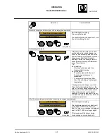
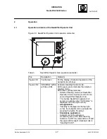
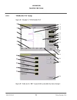
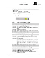
Table 4
Operating and monitoring elements for the first display
(after switching ON the NautoPilot Operator Unit)
Function
Figure 22/1
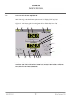
Indicates the type of NautoPilot: NP 5100, NP 5300, NP 5400 or
NP 5500.
Figure 22/2
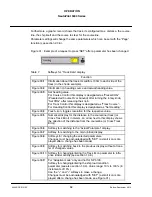
Alert and status bar (top bar of the display). Alerts and status informa-
tion are displayed alphanumerical. They must be acknowledged.
For more information see the NautoPilot Operator Unit Service Manual.
Figure 22/3
Indicates the actual heading value from the selected heading source.
Figure 22/4
Indicates the selected heading source.
Possible heading sources are:
-- Gyro
-- GPS
-- Mag
Uncorrected Magnetic Heading (magnetic heading without
correction values for variation/deviation)
Figure 22/5
Indicates the operation mode / status of the Autopilot:
Heading Ctrl, see also section 1.4.3
( -- all types of NautoPilot -- )
or
Course Ctrl, see also section 1.4.4
( -- not for NautoPilot 5100 -- )
or
Track Ctrl, see also section 1.4.5
( -- all types of NautoPilot -- )
or
Override, see also section 1.4.8
( -- all types of NautoPilot -- )
or
Manual, see also section 1.4.7
( -- all types of NautoPilot -- )
or
Standby, see also section1.4.2
( -- all types of NautoPilot -- )
or
------------, see section 1.4.2
( -- all types of NautoPilot -- )
Figure 22/6
Indicates selected mode Economy or Precision, selectable via the soft-
key “Eco/Prec” (Figure 22/18)
Not for NP 5100 or if the “Adaptive mode” is not configured.
Otherwise the softkey is designated as “Para/Mem”.
Figure 22/7
Indicates the difference between actual heading and set heading in a
tendency bar structure.
For Course Control mode this bar is designated as
“Distance to Courseline”.
See also section 2.3.1.
For Track Control mode this display is designated as
“Cross Track Error”.
Figure 22/8
Indicates the set heading value from a manual steering control unit
(Handwheel/Tiller/Rotary knob).
This display also acts as a softkey; by touching it, the display resolution
is changed and the small icon (Figure 22/9) changes.
For Course Control mode this display is designated as
”Set Course Over Ground”.
For Track Control mode it is designated as “Track Course”.
Figure 22/9
Resolution icon.
Softkey to switch the resolution of the set heading value between
1
and 1/10
.
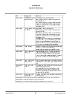
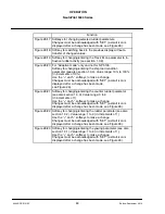
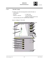
Figure 22/10 Softkey for switching between night and day modes.

