OPERATION
AUTOPILOT
NautoPilot 5000 Series
87
4002.DOC010102
Edition: September 2014
2.3.6.4
Limit values
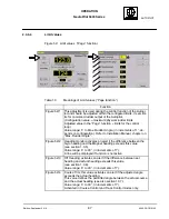
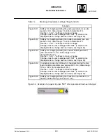
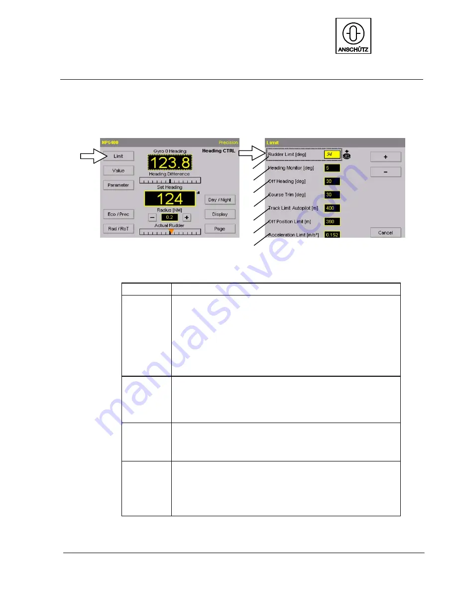
Figure 52: Limit values (”Page” function)
1
2
3
4
5
6
7
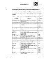
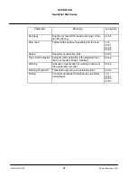
Table 13
Meanings of Limit values (”Page function”)
Function
Figure 52/1
This adjustment is used during the control function of the Autopi-
lot and should be adjusted within the configured limits. It sets lim-
its for command rudder output of the Autopilot.
(Configuration value = maximum/physical rudder limits
Adjusted value in the ”Page” function = limits for the control
loop).
Value range: 5
to Max. Rudder Angle, (in increments of 1
, de-
pends on configuration). Refer to Installation Manual, chapter on
“Max. Rudder Angle”.
Figure 52/2
Heading monitor activates an alert if the difference between the
Gyro heading and the Magnet heading exceeds this value
(see section 1.3.5).
Value range: 5
to 30
, (in increments of 1
).
A line will be displayed if function is not active.
Figure 52/3
Off Heading; activates an alert if the difference between set
heading and actual heading exceeds this value
(see section 1.3.6).
Value range: 5
to 30
, (in increments of 1
).
Figure 52/4
Course Trim; this value activates an alert if the adjusted angle
exceeds the actual heading.
This value defines the permitted angle between the actual course
and the actual heading (see also section1.3.7).
Value range: 5
to 30
, (in increments of 1
).
Activated in Course Control and Track Control modes only.

