V1.1
Shanghai Empower Technologies Co., Ltd. © Copy Right
www.empower.cn
BM114 SERIES 6KW Laser Cutting Head User Manual
6 | 11
2 Machinery Installation
2.1 Hole site installation installation
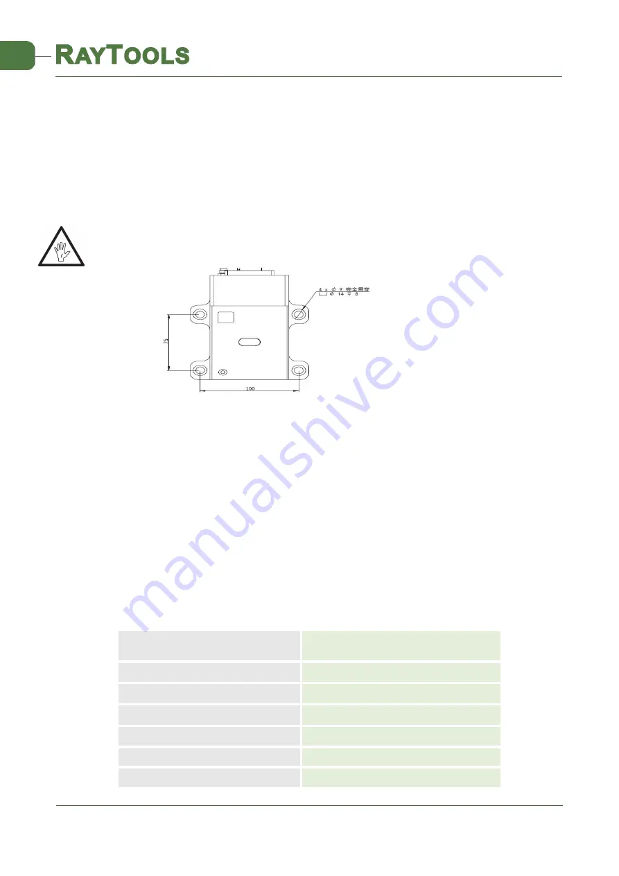
BM114 laser machining head and the fixed mounting hole size and position of the machine tool are shown in
Figure 3.1. Customers are advised to Install the laser head perpendicular to the machined surface as requested
and make sure the laser head is locked, which is one of the premises to ensure the follow up sable cutting effect.
CAUTION: the Z-axis sliding base for fixing laser processing head should be connected with machine tools
and keep a good grounded.
2.2 Connection of Water Pipe and Gas Pipe
2.2.1
Water-cooled interface
BM114 laser processing head has 3 sets of water-cooled channels which direction of water entry and exit can
be arranged arbitrarily. It is important to note that when the laser power is greater than 500 watt hours, it is
recommended to use water-cooled.as you can see from Figure 3.2, the position and amount of the water
interface, and the right table details the recommended flow velocity.
The design of this water-cooled interface is closed loop water-cooled system, and it also can be used
equipped with external water supplied but subjected to the requirements of the list.
Outer diameter of water pipe
caliber
6mm
Minimum flow speed
1.8 l/min(0.48gpm)
Entry pressure
170-520kPa(30-60 psi)
Entry temperature
≥room tempreture /
>
dew point
Hardness (relative to CaCO3)
<
250mg/liter
PH range
6 to 8
Particles size available
Diameter less than 200 microns
Figure 3.1 — Hole site installation


