V1.1
Shanghai Empower Technologies Co., Ltd. © Copy Right
www.empower.cn
BM114 SERIES 6KW Laser Cutting Head User Manual
8 | 11
2.3 Connection of Cutting Head Cable
This paper mainly introduces the connection between the cable and the cutting head. The control section of
the driver and the connection refer to the wiring diagram of each series of system.
2.3.1
Connection of Cutting Head and Cable
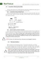
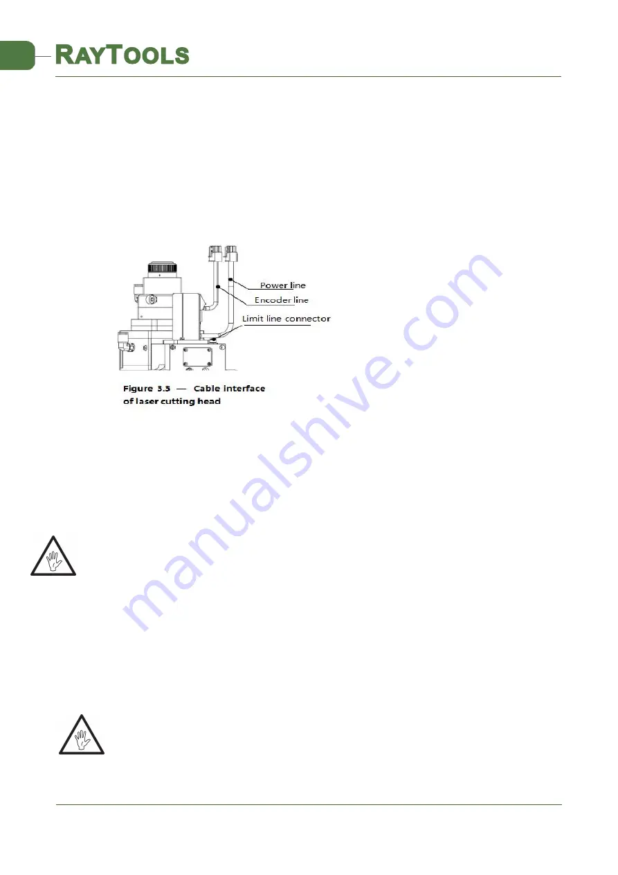
Connect the corresponding connector of cutting head with motor power cable, encoder cable, sensor cable
respectively (as shown in figure 3.3). After the proper length is reserved, the cable is inserted into the track groove
of the machine tool and fixed.
2.3.2
Cable Connection and Driver Connection
Connect motor power wire and encoder wire with the corresponding interface of driver according to the
definition in cable sleeve. The wiring of the drive and limit sensor cables is shown in the wiring diagram of the
various wiring systems attached.
Caution: The limiting sensor is divided into high level output and low level
output, and the two are normally closed output mode(high level and low level signal are output by the sensor
when not triggered); electric relay should be self installed when necessary to carry on the high-low level or the
normally open and normally closed conversion.
CAUTION:
All wiring is in the state of power failure, and the power can be debugged after inspection.
2.4 Fiber Input Interface
BM114 is suitable for most industrial laser generators. It is equipped with collimating mirror assembly
The connection between the end of the fiber and the cutting head is called fiber interface. Commonly used
fiber connectors include QBH, QD, etc, and every fiber interface has its unique fixation method. Please refer to
corresponding instruction of fiber interface. Figure 5 shows the installation interface of QBH connector.
WARNING:
The optical devices must be kept clean and all dust must be removed before use. If the laser
head is vertically inserted in the optical fiber, the laser head must be rotated 90 degrees to the
horizontal level and then inserted into the optical fiber to prevent dust from entering the interface and
falling on the surface of the lens. Upper limitng in the fiber before fixing the laser head.


