background image


V1.0 

RayTools AG. © Copy Right


11 | 19


www.raytools.net 

BT240S 3KW 2D Laser Cutting Head User Manual 

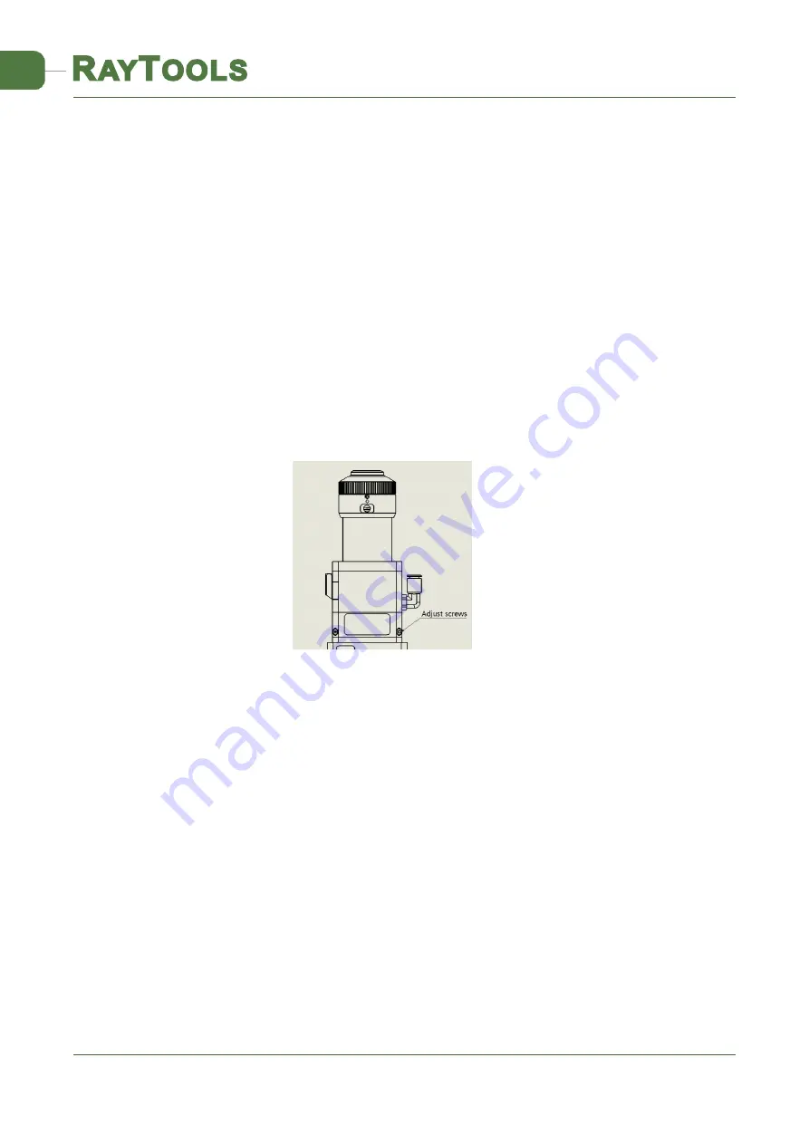
2. The 2.5 mm internal hexagonal wrench can be used to loosen or tighten the adjusting screw until the 
light beam is in the middle of the nozzle. 

Make sure that the laser beam exits the center of the nozzle. One common method is tape dotting: 
1. Take a piece of transparent tape and flatten it directly under the end face of the center hole of 

the nozzle; 

2. Turn on the red light inside the laser to find and observe the position of red light relative to the 

center of the nozzle. Adjust the screw to make the red light spot to the relative central position of the 
nozzle; 

3. The next step is to turn on and adjust the power range of the laser generator from 80W to 100W, 

and perform manual dotting; 

4. Tear off the adhesive tape to check whether the hole is located in the center of the nozzle; 
5. Repeat the above steps to find the best relative nozzle center position of the light beam; 
Such center-regulation requires a series of adjustments, which is the basic operation of any laser 

center-regulation. 


2.6    Adjust the Focus Position


BT240S is configured with a focusing rotating scale ring, which is used to move the focus position 

to optimize laser cutting technology. The lens have 20mm reciprocating stroke. Before cutting, it is 
necessary to confirm the focal point. When leaving factory, the "zero focus" also corresponds to the 
window "0" and the rotating ring scale "0". There are many ways to find the focal point, one of which 
is to apply masking paper directly under the nozzle of the laser cutting head:       

1. Directly adjust the laser head to the 0 scale ("ex-factory zero focus"), that is, the window scale 

is adjusted to "0". At this time, the scale of the rotating ring should be 0. 

2. Adjust the scale of the focal length compass, adjust from +2 to -2, laser power is recommended 

to be 80-100w; 

3. Then open the laser and drill a hole on the masking paper within 0.5mm each move (the smaller, 

Figure 5-2 QBH Beam Center-regulating


Summary of Contents for BT240S Series

Page 1: ...BT240S SERIES Email sales raytools net Add EMMENTALSTRASSE 96 CH 3414 OBERBURG SWITZERLAND 3000W 2D Laser Cutting Head User Manual...

Page 2: ...for your choosing our product This manual makes a detail introduction about the use of BT240S laser cutting head including installation setup operation and service etc Please directly contact us if y...

Page 3: ...sertion Direction Adjustment of Fiber Interface 8 2 5 Adjust 10 2 5 1 QCS Beam Center regulating 10 2 6 Adjust the Focus Position 11 3 Maintenance 13 3 1 Clean the Lens 13 3 2 Removal and Installation...

Page 4: ...flow and nozzle cooling design built in water cooling unit and fine adjustment of focus position and other characteristics can fully meet the industrial laser processing environment of thin plate medi...

Page 5: ...Figure 2 the laser head includes four basic units namely 1 collimation module component CM 2 focusing module component FM 3 protection window module component WM and 4 nozzle module component TM to m...

Page 6: ...f the installation hole is shown in Figure 2 It is suggested that the client should install the laser head vertically on the processing board face according to the requirements of the drawing and ensu...

Page 7: ...The recommended water speed is listed below in detail and please adjust the temperature of the cooling water at room temperature of 5 This water cooled interface is designed as a closed loop water coo...

Page 8: ...le and the laser head parts will be damaged at the same time Note the gas pipeline on the customer site is likely to hide condensate water pite tape for joint sealing and other impurities after valvin...

Page 9: ...e sealed with a clean self sealing bag so as to avoid dust falling into it 2 As shown in Figure 3 please align the center hole of the protective cap to the optical fibre splice and put it on the optic...

Page 10: ...cond level locking 4 Swing the fiber connector to the right and left and up and down to check if the QBH fiber is completely fixed Complete the locking procedure Note the picture effect is for referen...

Page 11: ...en in place The optical fiber insertion method of BT240S QCS interface is shown in Figure 4 2 1 Loosely locking rings 1 and 2 2 Horizontally insert the fiber interface 3 Lock the locking rings 1 and 2...

Page 12: ...e steps to find the best relative nozzle center position of the light beam Such center regulation requires a series of adjustments which is the basic operation of any laser center regulation 2 6 Adjus...

Page 13: ...slightly loosen Screw 3 to adjust the scale block to the 0 scale line and tighten Screw 2 and Screw 3 again then the on site actual zero focus is coincident with the laser head focusing 0 scale indic...

Page 14: ...note avoid the fingertip touching the surface of the lens so as to leave traces 4 Put the lens facing to eyes and hold the absorbent cotton stick with the right hand Wipe the lens gently in single dir...

Page 15: ...he lock nut Pull out the protective lens holder by holding both sides of the drawer lens holder Press the edge of the lens with fingers push one side of the lens of the spring seal ring from the lens...

Page 16: ...damaged Wipe off the dust on the surface of BT240S Use a 3mm internal hexagonal wrench to unscrew the screws above the optical fiber collimation mirror as shown in Figure 11 Place it in a clean place...

Page 17: ...ng cover on the fiber to prevent it from being damaged 3 2 4 Removal and Installation of Focus Lenses The collimating lens can be replaced when the laser head is removed from the machine This manual i...

Page 18: ...enter of the nozzle hole if it is not in the center it is necessary to carry out center regulating operation again 3 3 Replace Nozzle Connector In the process of laser cutting the laser head will inev...

Page 19: ...Copy Right 18 19 www raytools net BT240S 3KW 2D Laser Cutting Head User Manual 3 4 Replace Nozzle Unscrew the nozzle Screw a new nozzle onto the nozzle connector Make capacitor calibration once again...

Reviews: