1/20/2015 (3:46 PM)
2034vx & 2034vxa v6.0.doc
3.3
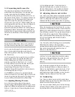
Pressurizing the Pressure Pot
The pressure pot opening is located inside the
cabinet below the metal grate. The pressure pot
closure cap is attached to a linkage, which is
movable from the pressure pot closure lever (L) on
the left side of the cabinet. The purpose of the lever
and linkage is to lift the pressure pot closure cap
upward to contact the pressure pot rubber seal
located at the top of the pot. While holding the cap
in the up position with lever (L) the air is turned on,
this fills the pot, and presses the cap securely
against the pressure pot rubber seal, sealing the pot
and pressure inside. When the cap is in the down
position there is a gap between the cap and the seal,
which allows the abrasive from blasting to re-enter
the pot.
! WARNING
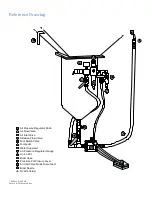
Ensure that the Blast Hose (K) is in the cabinet at
all times when the pressure pot is under pressure.
3.3.1
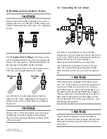
Locate the Pressure Pot Closure Lever (L) and
move it back and forth rapidly several times to
shake off any abrasive that may be sitting on top of
the closure cap.
3.3.2
Now push the lever away from you to lift the
pressure pot closure cap against the rubber seal.
While holding the lever firmly in this forward
position, open the Air Inlet Valve (C). Count 3
seconds and then release the Pressure Pot Closure
Lever (L). The pot should be closed and
pressurizing at this point. The Air Pressure
Regulator Gauge (H) should rise to the factory pre-
set blasting pressure of 30 psi.
3.3.3
NOTE
: If you hear air escaping inside the
cabinet, turn off lever (C) and try again. If for some
reason you cannot get the pressure pot closure cap
to seal, call Rayzist and ask for technical help.
3.4
Adjusting Blasting Pressure.
3.4.1
After pressurizing the pot the pressure
regulator gauge (H) should read about 30 psi. If the
gauge has a different reading make an adjustment as
follows: Unlock the Air Pressure Regulator Knob
(A) by pulling upwards. Twist clockwise to
increase blast pressure or counter clockwise to
decrease blast pressure. Set regulator to desired
pressure, and then press down to lock the knob.
3.5
Adjusting Abrasive and Air flow
3.5.1
Turn on the dust collector and lights and check
the plastic dust bag on the dust collector to make
sure it is collapsing; this indicates it is properly
installed and has sealed the dust collector opening.
! NOTICE
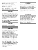
When first stepping on the Foot Pedal (F), you may
experience a thick burst of abrasive media from the
blasting tip, which should smooth out to a constant
flow of abrasive and air. This occurs when Abrasive
Flow Valve (D) is open too far. When starting to
blast you should hold the blasting tip away from the
item you are blasting until abrasive media is
flowing smoothly.
3.5.2
Put on the rubber blasting gloves and hold the
Blast Hose (K) and have the tip pointing
downwards towards the grate about 6" to 8" away.
Step on the foot pedal and watch the flow of
abrasive as described above.
! NOTICE
Air Flow Valve (B) adjusts how much air pushes
the abrasive through the Blast Hose (K). Less air
flow = more abrasive. More air flow = less
abrasive.
3.5.3
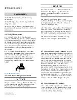
If necessary adjust Air Flow Valve (B) to
achieve the proper balance of abrasive and air. If
there is too much abrasive open valve more, if not
enough close the valve slightly. If the abrasive is
pulsating between thick and thin, you may need to
slightly close the Abrasive Flow Valve (D).
3.6
Sandcarving
3.6.1
Turn on cabinet power switch located above
the right cabinet access door; the dust collector and
lights should both begin operating.
3.6.2
Use (provided) rubber gloves before blasting.
(18mil or thicker rubber or latex safety gloves can
be purchased from a local hardware store.).
Summary of Contents for 2034vx
Page 1: ... 2034vx 2034vxa Sandcarving System ...
Page 2: ......
Page 19: ......
Page 20: ...RAYZIST COM 800 729 9478 ORDER ONLINE WWW RAYZIST COM STORE ...


