Contents 4
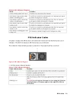
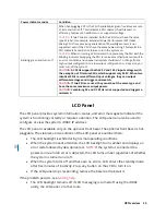
Figure 18. PSU Indicator Diagram ............................................................................................................... 23
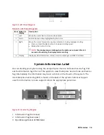
Figure 19. LCD Panel Diagram ..................................................................................................................... 24
Figure 20. Service Tag Diagram ................................................................................................................... 25
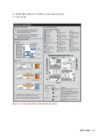
Figure 21. Service Information with System Touch Points ......................................................................... 26
Figure 22. Front View of V14 ...................................................................................................................... 27
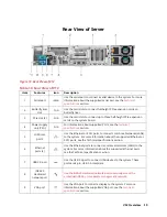
Figure 23. Rear View of V14 ........................................................................................................................ 28
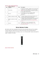
Figure 24. Left control panel without optional iDRAC Quick Sync 2.0 indicator ........................................ 29
Figure 25. Left control panel with optional iDRAC Quick Sync 2.0 indicator .............................................. 30
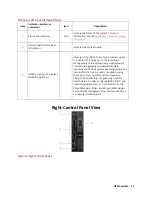
Figure 26. Right Control Panel .................................................................................................................... 30
Figure 27. Drive indicators .......................................................................................................................... 31
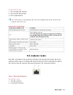
Figure 28. NIC Indicator Diagram ................................................................................................................ 32
Figure 29. PSU Indicator Diagram ............................................................................................................... 33
Figure 30. LCD Panel Diagram ..................................................................................................................... 35
Figure 31. Service Tag Diagram ................................................................................................................... 35
Figure 32. Front View of A8 ........................................................................................................................ 37
Figure 33. Rear View of A8 .......................................................................................................................... 37
Figure 34. Drive indicators .......................................................................................................................... 38
Figure 35. NIC Indicator Diagram ................................................................................................................ 39
Figure 36. PSU Indicator Diagram ............................................................................................................... 40
Figure 37. LCD Panel Diagram ..................................................................................................................... 41
Figure 38. LED Behavior, Express Service Tag, Configuration and Layout .................................................. 43
Figure 39. System touchpoint, electrical overview, jumper settings, and memory information ............... 44
Figure 40. Front View of M4 ....................................................................................................................... 45
Figure 41. Rear View of M4 ......................................................................................................................... 45
Figure 42. Left Control Panel ...................................................................................................................... 46
Figure 43. Right Control Panel .................................................................................................................... 46
Figure 44. Drive Carrier Layout ................................................................................................................... 47
Figure 45. NIC Indicator Lights .................................................................................................................... 48
Figure 46. PSU Indicator .............................................................................................................................. 48
Figure 47. Service Tag ................................................................................................................................. 50
Figure 48. Front and Rear Touchpoints for M4 ........................................................................................... 50
Figure 49. System Dimensions for V8, V12, and V14 .................................................................................. 51
Figure 50. Dimensions for A8 ...................................................................................................................... 52
Figure 51. Dimensions for M4 ..................................................................................................................... 53
Figure 52. Rail Kit Contents ......................................................................................................................... 59
Figure 53. Installing and Removing Tool-Less Rails ..................................................................................... 60
Figure 54. Installing and Removing Tooled Rails ........................................................................................ 61
Figure 55. Installing the System in a Rack ................................................................................................... 62
Figure 56. Removing System from the Rack ............................................................................................... 63
Figure 57. Engaging and Releasing the Slam Latch ..................................................................................... 64
Figure 58. Routing the Cables ..................................................................................................................... 65
Figure 59. Right Control Panel View ........................................................................................................... 67
Figure 60. BIOS System Setup Main Menu ................................................................................................. 71
Figure 61. BIOS Device Settings Menu ........................................................................................................ 72
Summary of Contents for A8
Page 1: ...rcgs20200916 2020 2020 2020 2020 2020 2020 2020 2020 2020 ...
Page 27: ...V12 Overview 26 Figure 21 Service Information with System Touch Points ...
Page 75: ...RAID Storage 74 Select Virtual Disk Management Figure 63 PERC Adapter Server Profile View ...
Page 81: ...RAID Storage 80 Select Create Virtual Disk Figure 69 Create Virtual Disk ...
Page 82: ...RAID Storage 81 Select RAID level Figure 70 Select RAID Type ...
Page 83: ...RAID Storage 82 Select Physical Disks Figure 71 Select Physical Disks ...
Page 85: ...RAID Storage 84 Scroll up and Click Apply Changes Figure 73 Apply Changes ...
Page 86: ...RAID Storage 85 Select OK Figure 74 Confirm Completion ...
Page 89: ...RAID Storage 88 Confirm and Click Yes Figure 77 Confirm Operation ...
Page 96: ...RAID Storage 95 Verify all settings and if correct click Finish Figure 84 Complete the Wizard ...


