

Specifications 51
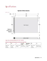
System Dimensions
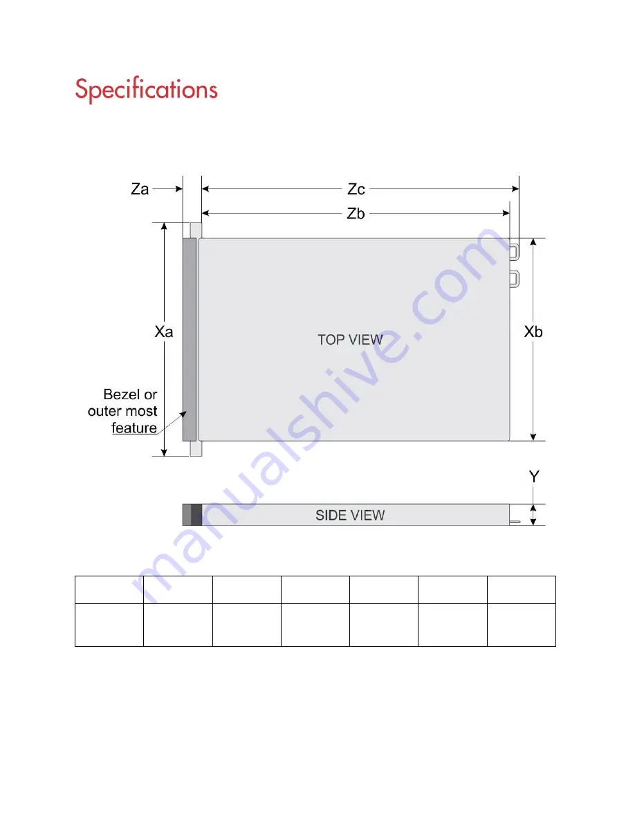
V8, 12, 14
Figure 49. System Dimensions for V8, V12, and V14
Table 35. System Dimensions for V8, V12, and V14
Xa
Xb
Y
Za (with
bezel)
Za (without
bezel)
Zb
Zc
482.0 mm
(18.97
inches)
434.0 mm
(17.08
inches)
86.8 mm (3.41
inches)
35.84 mm
(1.41 inches)
22 mm (0.87
inches)
647.07 mm
(25.47
inches)
681.755 mm
(26.84 inches)
Summary of Contents for A8
Page 1: ...rcgs20200916 2020 2020 2020 2020 2020 2020 2020 2020 2020 ...
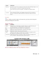
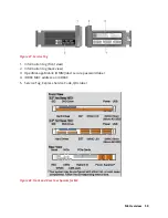
Page 27: ...V12 Overview 26 Figure 21 Service Information with System Touch Points ...
Page 75: ...RAID Storage 74 Select Virtual Disk Management Figure 63 PERC Adapter Server Profile View ...
Page 81: ...RAID Storage 80 Select Create Virtual Disk Figure 69 Create Virtual Disk ...
Page 82: ...RAID Storage 81 Select RAID level Figure 70 Select RAID Type ...
Page 83: ...RAID Storage 82 Select Physical Disks Figure 71 Select Physical Disks ...
Page 85: ...RAID Storage 84 Scroll up and Click Apply Changes Figure 73 Apply Changes ...
Page 86: ...RAID Storage 85 Select OK Figure 74 Confirm Completion ...
Page 89: ...RAID Storage 88 Confirm and Click Yes Figure 77 Confirm Operation ...
Page 96: ...RAID Storage 95 Verify all settings and if correct click Finish Figure 84 Complete the Wizard ...


