background image

16

FUTERA II INSTALLATION AND OPERATION INSTRUCTIONS

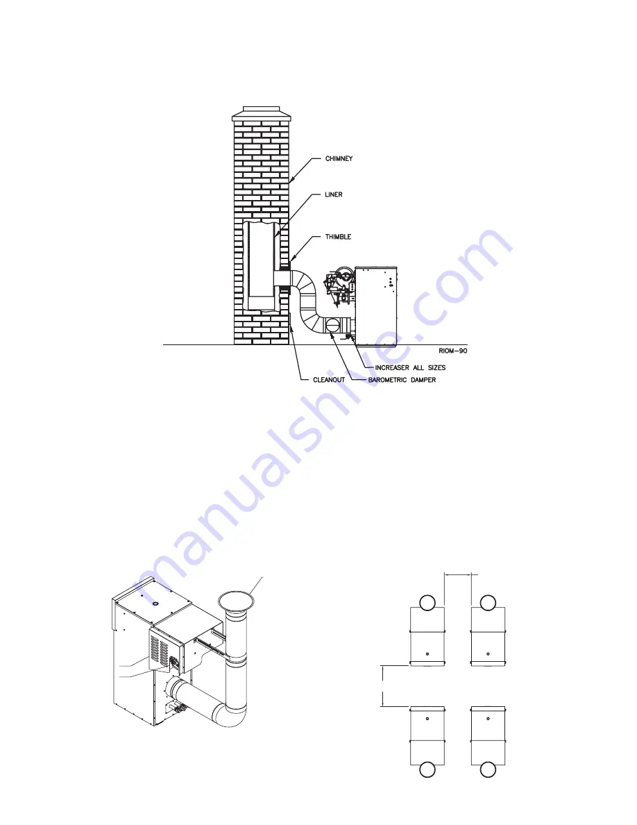
Figure 10 – Outdoor Venting

 Figure 11 – Multiple Outdoor Units

Figure 9 – Vertical Venting using a Masonry Chimney 

OUTDOOR VENTING

When installed outdoors the Futera III must be fitted with 
the factory supplied outdoor hood, air intake adapter with 
filter and exhaust terminal, see Figure 7A. Multiple units 
must be spaced per Figure 7B.

The boiler/heater must be at least 

2 ft

,  .62 m from any 

door, window or gravity air inlet into any building and at 
least 

3 ft

1 m from any overhang unless local codes dictate 

differently. 

Avoid locations where wind deflection off of adjacent walls, 
buildings or shrubbery might cause a downdraft. The 
unit(s) shouild be located at least 

3 ft

1 m from structures. 

Outdoor installations are not recommended in areas where 
the danger of snow blockage exists.

CAUTION: Do not place the boiler/water heater in a 

location that would subject it to runoff from adjacent 

buildings or damage may occur voiding the warranty!

DISCHARGE VENT

GAS TRAIN COWLING

AIR INLET

UNDER COWLING

RIOM-60 REV. A

 2 FT

(0.62 M)

 3 FT

(1 M)

Summary of Contents for FUTERA II 1000

Page 1: ...uction dust and particulate particularly drywall dust will cause contamination of the burner resulting in possible severe personal injury death or substantial property damage The boiler can only be op...

Page 2: ...as Fired Low Pressure Steam and Hot Water Boilers ANSI Z21 56 CSA 4 7 Gas Fired Pool Heaters Canada Only Each unit has been constructed and hydrostatically tested for a maximum working pressure of 160...

Page 3: ...er heater in a location that would restrict the introduction of combustion air into the unit or subject it to a negative pressure see GENERAL VENTING GUIDELINES 6 NEVER place this boiler water heater...

Page 4: ...st be given to the blockage effects of louvers grills and screens Screens must have a minimum mesh size of 1 4 in 6 4 mm If the free area through a louver or grill is not known ducts should be sized p...

Page 5: ...the horizontal combustion air pipe on installations that used the Direct Vent option is 60 ft 18 3 m The maximum equivalent length for the horizontal combustion air pipe on installations that use the...

Page 6: ...61 cm from the center line of the terminal E Clearance to unventilated soffit F Clearance to outside corner G Clearance to inside corner H Clearance to each side of center line extended above meter re...

Page 7: ...3 kW and 100 000 Btuh 30 kW 36 in 91 cm for appliances 100 000 Btuh 30 kW 4 ft 1 2 m below or to side of opening 1 ft 300 mm above opening C Clearance to permanently closed window D Vertical clearance...

Page 8: ...or balcony is fully open on a minimum of two sides beneath the floor NOTES 1 In accordance with the current CSA B149 1 Natural Gas and Propane Installation Code 2 In accordance with the current ANSI Z...

Page 9: ...meters gas meters regulators and relief equipment and not less than 7 ft 2 1 m from any adjacent public walkway The bottom of the vent terminal s shall be located at least 5 ft 1 5 m above the air in...

Page 10: ...10 FUTERA II INSTALLATION AND OPERATION INSTRUCTIONS Figure 1 Air Intake Vertical or Thru Wall Figure 2 Venting Thru Wall Vertical...

Page 11: ...gle or multiple units exhaust and combustion air terminals must be installed on the same plane outside wall in order to prevent pressure differences due to prevailing winds In cold climates double wal...

Page 12: ...AND OPERATION INSTRUCTIONS Figure 5 Vertical Air Intake and Venting for Direct Vent System Figure 6 Combination Direct Vent Systems 10 FT 3 1 m 4 FT 1 2 m 5 FT 1 5 m 1 5 FT 0 5 m 5 1 2 FT 1 7 m 1 5 FT...

Page 13: ...venter for the boiler water heater see Table 4 Follow the power venter manufacturer s installation instructions Table 4 Power Venter Sizes VERTICAL CHIMNEY VENT NEGATIVE PRESSURE CATEGORY I The Futer...

Page 14: ...ingle wall vent connection with at least 3 corrosion resistant sheet metal screws Always provide a minimum clearance of 6 in 152 mm between single wall vent pipe and any combustible materials Type B1...

Page 15: ...15 FUTERA II INSTALLATION AND OPERATION INSTRUCTIONS Figure 8 Vertical Venting with a Metal Chimney System...

Page 16: ...r window or gravity air inlet into any building and at least 3 ft 1 m from any overhang unless local codes dictate differently Avoid locations where wind deflection off of adjacent walls buildings or...

Page 17: ...marche Suivre les instructions d allumage R gler le thermostat de fa on que l appareil fonctionne de fa on continue e Test for spillage at the draft hood relief opening after 5 minutes of main burner...

Page 18: ...water mix that prevents foaming Air entrapped within foam significantly decreases heat transfer and can result in damage to the heat exchanger Products such as DOWFROST DOWTHERM UCARTHERM or an equiva...

Page 19: ...4 C The adjustable pump delay turns the pump on each time the burner fires and runs the pump for 6 to 600 seconds after the call for heat is satisfied CAUTION A temperature rise outside of the range...

Page 20: ...econdary systems In order to prevent boiler s short cycling the system flow must be equal to or higher than the boiler s local flow Low Return Water Temperatures To prevent the problems associated wit...

Reviews: