10
Finned copper tube gas boilers & water heaters – Boiler manual
FTXLF-IOM-HN-1-110308 Copyright 2008 Mestek, Inc.
VENT OPTION 2: VERTICAL CHIMNEY VENTING
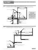
Figure 5
Vertical venting — with a metal chimney system
See Figure 4, page 7 for minimum pipe diameters.
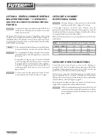
Figure 6
VENT OPTION 2: VERTICAL CHIMNEY VENTING
Vertical venting — using a lined masonry chimney
See Figure 4, page 7 for minimum pipe diameters.
option 2: VerticAL VentinG
positiVe pressUre, cAteGory iV
FiGUre 5 or FiGUre 6
(VENT PIPE EquIVALENT LENGTH uP TO100 FEET MAxIMuM)
Masonry chimneys, when used, must be lined with a
metal liner certified for Category IV venting.
A thorough inspection of the masonry chimney must be
performed to ensure that the chimney is clean, properly construct-
ed, lined and sized. Exterior masonry chimneys should not be used
unless properly lined to prevent condensation and draft problems.
Table 5 lists the equivalent breeching and flue sizes required for the
boiler/water heater.
Vent connections
Locate the boiler/water heater as close to the chimney as
possible. Use the shortest, straightest vent connector possible for the
installation. If horizontal runs exceed 5 ft, 1.5 m they must be sup-
ported at 3 ft, 0.9 m intervals with overhead hangers.
The vent connector should be sloped up toward the chimney at a
minimum rate of ¼ in/ft, 21 mm/m. On masonry chimneys the
connector must terminate flush with the inside of the chimney flue,
Figure 8, page 13.
Always provide a minimum clearance of 6 inches, 152 mm between
single wall vent pipe and any combustible materials.
Failure to maintain minimum clearances between vent
connectors and any combustible material can result in a
fire causing extensive property damage, severe personal
injury or death!


