13
Finned copper tube gas boilers & water heaters – Boiler manual
FTXLF-IOM-HN-1-110308 Copyright 2008 Mestek, Inc.
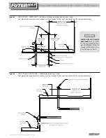
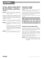
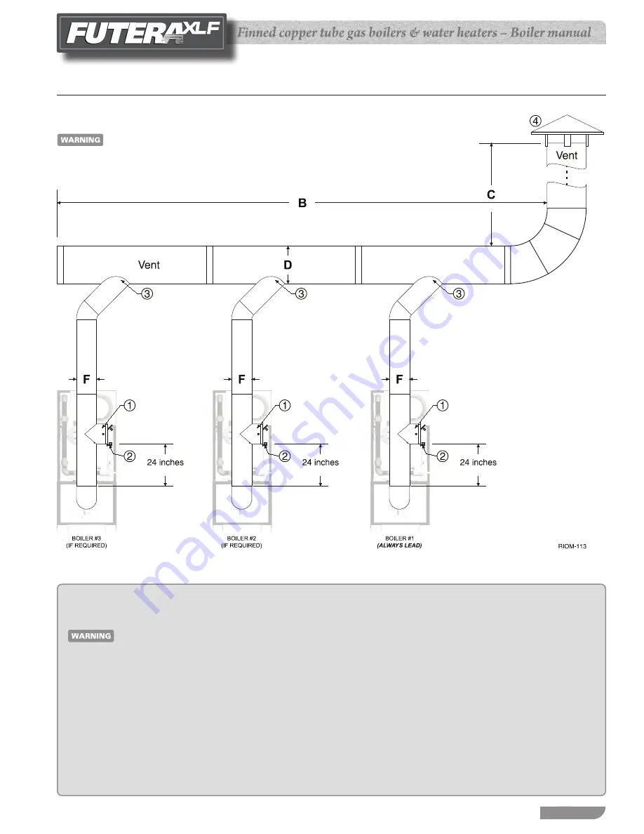
OPTION 4: VERTICAL CHIMNEY VENTING — Vertical venting — multiple-boiler installations
Figure 8
See Table 5, page 12 for minimum riser diameter (dimension F)
Legend for Figure 8
The boiler nearest the vertical chimney must always
be fired first.
A negative pressure of 0.02 to 0.08 inches w.c. is
required in each boiler's riser when all boilers are
operating at full input.
Provide clearance from the boiler of no less than
6 inches to combustible surfaces or 24 inches for
service.
A barometric damper must be installed on the riser of each boiler,
1.
24 inches above the vent elbow. [Exception: If the vent system is
designed using accepted engineering practices, and the design
calculations prove there is no need for barometric dampers, the
barometric dampers may be omitted.] When required by ap-
plicable codes, install a thermal spill switch on each barometric
damper.
Install a thermal spill switch on each barometric damper (when
2.
required by applicable codes).
Connect each boiler riser to the common vent with a y connec-
3.
tion only.
Install an approved vent cap at the vent termination.
4.
DIMENSIONS:
5.
B
breeching length
C
chimney height
D
breeching diameter
F
riser diameter (no smaller than the dimension given in
Table 5, page 12)
Size the chimney and breeching per local codes and vent pipe
6.
manufacturer's recommendations, using generally accepted
engineering practices.
DO NOT common vent more than the following
number of Futera XLF boilers:
XLF-3000
(4) boilers maximum.
XLF-4000
(3) boilers maximum.


