20
Finned copper tube gas boilers & water heaters – Boiler manual
FTXLF-IOM-HN-1-110308 Copyright 2008 Mestek, Inc.
Futera xLF Heat Exchanger Selection
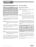
table 8
Futera xLF Pumping Performance Requirements
table 9
Water hardness
soft
normal
Hard
Heat exchanger type
Cupro-nickel
Copper
Cupro-nickel
Boiler model
GPM
ΔP
ΔT
GPM
ΔP
ΔT
GPM
ΔP
ΔT
mW-3000
speciAL
reQUirements
(call factory
or representative)
210
9.73
25.0
262 14.54 20.0
mW-4000
210 10.40 33.0
262 16.90 27.0
ΔT = Temperature change = (Outlet temp – Inlet temp) in
o
F
ΔP = Head loss = (Inlet pressure – Outlet pressure) in feet of water column
To achieve the proper flow rate, adjust outlet valve on heater piping to obtain correct ΔT
Call factory if grains of hardness is less than 3 or greater than 24.
Selection Table (Table 8) and the Pump-
ing Performance Table (Table 9). Scale free
operation can be achieved by using water
with a hardness between 8 and 18 and by
maintaining the pH between 5 and 9. Fol-
low the conditions listed under NORMAL
in the table. In some areas of the country ad-
ditional precautions must be observed due
to unusual characteristics of the local water
supply. Call the nearest RBI representative
for details.
To properly size the pump a grain hardness
and pH test must be taken at the installation
site before the order is placed. Proper pump
sizing will improve heater performance and
help ensure heater longevity.
expansion tank
An expansion tank or other means to control
thermal expansion must be installed in the
water heating system if back flow prevention
devices are installed.
pump requirements
This low-mass water heater requires a con-
tinuous mini-mum water flow for proper op-
eration. The low water flow switch provided
for this unit will shut down the water heater
if flow falls below the required minimum
level. Table 9 provides the heat exchanger
pressure drop chart and temperature rise
table. The temperature rise across the water
heater must never exceed 35
o
F, 19.4
o
C.
cold Water supply
The cold water supply must be piped to the
water heater’s outlet piping between the
water heater and the hot water storage tank.
This will prevent untempered water from en-
tering the water heater. See the Temperature
Rise Control section, page 19.
Two typical water heating systems are
shown in Figure 14, page 21 and Figure 15,
page 21.


