LCD INSTALLATION AND OPERATION INSTRUCTIONS
Page 28
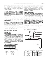
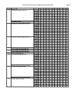
Table 20 - Pilot & Manifold Pressures
Table 21 - Combustion Readings
Instructions De Mise En Marche
1. ARRÊTEZ! Lisez les instructions de sécurité sur la
portion supérieure de cette étiquette.
2. Réglez le thermostat à la température la plus basse.
3. Coupez l’alimentation électrique de l’appareil.
4. Cet appareil est muni d’un dispositif d’allumage qui
allume automatiquement la veilleuse. Ne tentez pas
d’allumer la veilleuse manuellement.
5. Fermer la vanne manuelle d’arrêt d’alimintation de
gaz.
6. Attendre cinq (5) minutes pour laisser échapper tout
le gaz. Renifl ez tout autour de l’appareil, y compris
près du plancher, pour déceler une odeur de gaz.
Si vous sentez une odeur de gaz, ARRÊTEZ!
Passez à l’étape B des instructions de sécurité sur
la portion supérieure de cette étiquette. S’il n’y a
pas d’odeur de gaz, passez à l’étape suivante.
7. Ouver la vanne manuelle d’arrêt d’alimintation de
gaz.
8. Mettez l’appareil sous tension.
9. Réglez le thermostat à la température désirée.
10. Si l’appareil ne se met pas en marche, suivez les
instructions intitulées couper l’admission de gaz de
l’appareil et appelez un technicien qualifi é ou le
fournisseur de gaz.
To Turn Off Gas To Appliance
1. Set the operating control or thermostat to its lowest
setting.
2. Turn off all electric power to the appliance if service
is to be performed.
3. Close the manual main valves.
COUPER L’ADMISSION DE GAZ DE L’APPAREIL
1. Réglez le thermostat à la température la plus basse.
2. Coupez l’alimentation électrique de l’appareil s’il faut
procéder à l’entretien.
3. Fermer la vanne manuelle d’arrêt d’alimintation de
gaz.
CHECKING & ADJUSTMENTS
1. With the burners in operation, close the manual
shutoff valve in the gas supply line. As soon as the
main burner fl ames go out, open the manual shutoff
valve. A normal ignition sequence should take place.
If the burners fail to light, the gas valves will close
and the system will go into a 5-minute lock out
period. The fl ame sense module will then make a
second ignition attempt. If the unit won’t light ensure
that the gas piping is fully purged of air. Inspect the
ignition system and ensure that it is operating
properly.
2. To test the ignition safety shutoff device, close the
manual shutoff valve in the gas supply line. Within
5 seconds of main burner fl ame extinction, the main
gas valve solenoid should close with an audible
noise. After 10 seconds the module should lockout
and the trial for ignition end. After 5 minutes a
second trial for ignition should occur. Open the
manual shutoff valve in the gas supply line and reset
the ignition control system. A normal ignition
sequence should take place.
3. With the burners in operation, interrupt the power
to the control circuit by turning down the operator
or thermostat. The boiler/water heater should shut
down. Reset the operating control or thermostat. A
normal ignition sequence should follow.
On/Off
inches W.C.
mm W.C.
Pilot - NG
2.5 ± .3
63.5 ± 7.6
Pilot - LP
7.0 ± 2
177.0 ± 50.0
Low Fire
inches W.C.
mm W.C.
Manifold - NG
1.4 ± .2
35.5 ± 5.0
Manifold - LP
4.0 ± .5
101.6 ± 12.7
High Fire
inches W.C.
mm W.C.
Manifold - NG
2.5 ± .2
63.5 ± 5.0
Manifold - LP
9.3 ± .3
236.2 ± 7.6
Natural Fuel
Propane Fuel
CO
2
%
7.0 – 7.5 (low)
8.2 – 8.8 (low)
7.8 – 8.5 (high)
9.2 – 9.9 (high)
O
2
%
8.3 – 7.6 (low)
8.3 – 7.6 (low)
7.0 – 5.8 (high)
7.0 – 5.8 (high)

