30
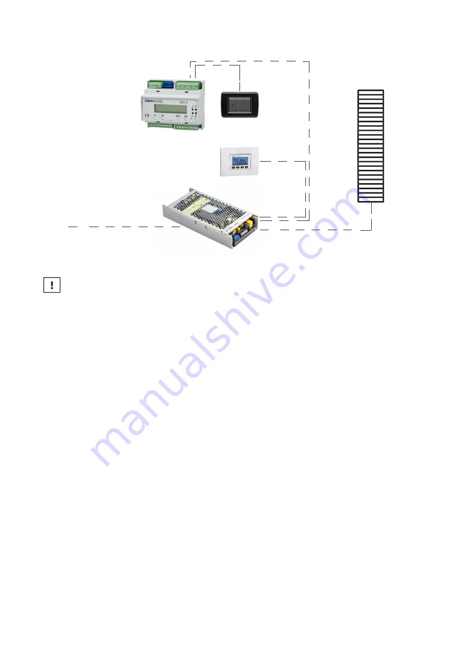
MORE PAD INDOOR
basic wiring diagram
Warning
BEFORE PROCEEDING WITH THE REMAINING STEPS
PERFORM THE FOLLOWING FUNCTIONAL CHECKS TO BE REPEATED FOR EACH POWER SUPPLY
DRIVER:
if necessary, adjust the voltage adjustment trimmer to correct the output value from the power
supply driver.
The purpose of the tests is to check whether there are any joints or connections which generate
excessive resistance resulting in an excessive voltage drop.
With positive electrical checks, check after about 15 minutes that the polymer is correctly heated.
Using an infrared camera, check that all strings are uniformly at temperature.
• primary circuit driver input voltage control
(230 V AC)
• driver output voltage control sub-circuit (36.0 V DC)
• secondary circuit voltage control to junction box (.........V DC)
• secondary circuit voltage control at crimp terminals
(… .....V DC)
• secondary circuit voltage control at the end of the string (35.5 V DC)
Alternatively, room control from
digital chronothermostat for ON-
OFF time and room temperature
consent
Primary power supply 230V
+ earth with protection by
differential magnetothermal
switch
PAD INDOOR
Alternatively, with ON-OFF direction from
RBM MORE SET2 control system. In the
case of integration with Pad Indoor, room
temperature management comes from the
same temperature probe as the radiant
system
Secondary line 36VDC


