background image

32

MORE PAD INDOOR

Valid for floor ONLY 

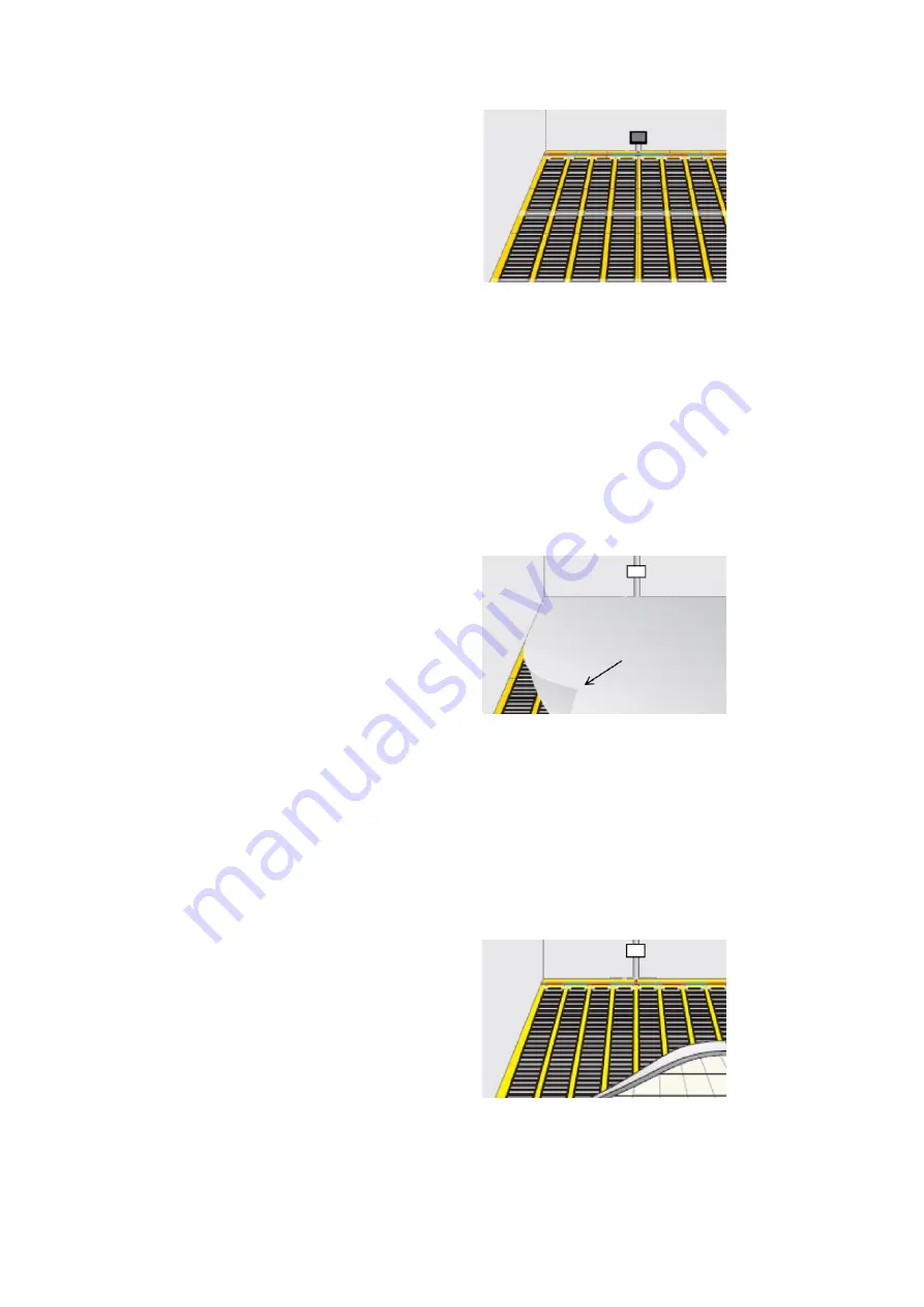
The protective sheet is to be laid over the entire floor 

surface, when the floor installation involves aggres-

sive cements and adhesives and/or when the laying 

centre distance exceeds 150 mm in order to favour 

the uniformity of the surface temperature. Along the 

joint lines of the sheet, overlap at least 5 cm.  

Use tape (packing tape or similar) to seal the edges 

of the protective sheet, preventing mortar or glue 

from penetrating underneath.

Valid for floor ONLY 

It is always advisable to use a self-levelling water-

based cement screed, with a minimum thickness 

of 2 cm, suitable for radiant floor systems. The 

self-levelling agent must be used to eliminate any 

irregularities caused by the wiring, as well as to 

prevent the joints from sagging. 

For the installation steps and instructions, follow the 

guidelines given by the manufacturer of the screed 

and the installer of the surface finish; the thickness 

of the self-levelling agent will depend on the type 

and size of the finish. 

Wait for the self-levelling agent to dry completely to 

avoid abnormal shrinkage and cracking, then switch 

the system on again in the test cycle for at least 24 

hours.

Valid for floor, wall or ceiling

Fasten the strings with metal staples on both sides 

and at each metre, taking care to lap only the

outside of the polymer by 2/3 mm, without touching 

the braids of the electrical struts.

Alternatively, use plastic nails or paper tape about 5 

cm long. The only purpose of fixing is to prevent the 

mat from shifting during the subsequent finishing 

stages

Another alternative to staples and nails to 

temporarily secure mats to the substrate, is solvent-

free reinforced double-sided tape, such as MAPEI 

Mapecontact, 240 mm wide.

Summary of Contents for PAD INDOO

Page 1: ...INSTRUCTION MANUAL MI3857_01 MORE PAD INDOOR ELECTRICAL INDOOR RADIANT HEATING SYSTEM MORE PAD INDOOR...

Page 2: ...ressive heating of the semiconducting polymer As the temperature of the mat increases the nanoparticles contained in the polymer compound move away from each other resulting in a progressive decrease...

Page 3: ...tion Plastering with water based cement mortar that can be smoothed over reinforcement mesh Ceramic wall tiles glued onto levelling compounds Dry application of plasterboard Integration of domestic he...

Page 4: ...ng system Check that the power supply is adequately protected as described in the following Chapter 9 PAD INDOOR system installation Before installation make sure that the electrical system if any has...

Page 5: ...cal circuit regarding ordinary or extraordinary maintenance operations must be carried out by professionally specialised personnel authorised according to Italian Ministerial Decree 37 2008 Refrain fr...

Page 6: ...uce consumption as it has reached its natural self regulating limit of approximately 30 C Self modulation depends on the semiconductor material and is limited to maximum 50 of initial consumption ther...

Page 7: ...ceramic coating with bonding The response times of the PAD INDOOR system are the same as those of a similar hydronic radiant system and depend on the mass to be energised and the average starting radi...

Page 8: ...Avoid contact with solvents as well as with glues and two component mortars that could compromise the long term stability of the technopolymer The surface of the mat can be covered with any type of b...

Page 9: ...RBM MORE advanced thermoregulation system associate the PAD INDOOR system with the control of window opening as well as the remote function control APP The control drivers included in the PAD system...

Page 10: ...ght IP65 SELV 3858 A Feeder to control very low voltage current modulating utilities with constant output voltage 230VAC 36VDC Power output 600 W watertight IP65 SELV 3858 B Feeder to control very low...

Page 11: ...for starting load limitation YES Remote on off consent YES Working environment temperature 40 70 C Max ambient working temperature peaks 90 C Dimensions LxDxH 252x90x43 8 mm Feeder weight 1 9 kg Mat...

Page 12: ...S Working environment temperature 40 55 C Max ambient working temperature peaks 90 C Dimensions LxDxH 280x144x48 5 mm Feeder weight 3 9 kg DRIVER of power supply 1000W Electrical power supply 90 264 V...

Page 13: ...n assisted heat output NO At nominal heat output elmax 0 035 kW Type of heat output room temperature control indi cate only one option At minimum heat output elmax 0 035 kW single stage heat output wi...

Page 14: ...without a heating system as a result of the non invasive work required The very low thermal inertia of the radiant element allows for fast system adjustments The heating element can be applied with a...

Page 15: ...n the case of the installation of heating systems equipped with radiant floor or ceiling panels and in the case of insulation from the inside the minimum heights of the living quarters provided for in...

Page 16: ...bicles 6 3 REGULATORY INFORMATION Special environments and applications IEC standard 64 8 part 7 Bathrooms have special environmental conditions that lead to greater risks especially related to the po...

Page 17: ...from the building envelope in the same way as any radiant air conditioning system This requirement is supplementary to any thermo technical dimensioning related to the energy efficiency of the buildin...

Page 18: ...lly placed in non heated or frost free conditions The chart below shows the self adjusting capacity of the technopolymer as the contact temperature of the mat changes PAD INDOOR TEMPERATURE C OUTPUT V...

Page 19: ...ed with the dimensioning of the extra low voltage power lines the cable route must be as short as possible in order to limit voltage drop as much as possible For the DC extra low voltage line provide...

Page 20: ...less of the size of the rooms and the electrical power installed the electrical system to be built must always be preceded by the project drawn up as provided for by Italian Ministerial Decree 37 2008...

Page 21: ...cated lacks or has limited ventilation for the correct operation of the equipment false ceiling built in electrical box etc A maximum of 10 m of PAD mat must be fed When the heating system is installe...

Page 22: ...nvironment where SELV safety is required When the heating system is installed in a special environment where SELV safety is required such as wet rooms or bathrooms A C B D C B D A IN line power supply...

Page 23: ...connection Use one or more terminals bridged bridged Remote consent ON OFF Closed contact ON Output voltage adjustment trimmer highlighted in red 1 V 8 GND 4 V 6 V 2 AC N 2 PV DIS 2 V 13 Vccs 5 V 3 7...

Page 24: ...referable not to place the power supply in quiet areas or within partitions separating bedrooms or reading rooms Avoid anchoring power supplies on large surfaces that can transmit vibrations Although...

Page 25: ...ngth specified in the installation plan Position the strings according to the centre distances specified in the installation plan When laying on the floor lay an electrical cable duct along the side c...

Page 26: ...t coloured cord for the extra low voltage line use red and black so that the two uprights and their polarities can be easily distinguished Mark the wire pair with an identification number so that it c...

Page 27: ...y cords of the mats with the backbone coming from the driver this must always be located in zone 3 If the power supply driver with SELV protection is not used the PAD INDOOR system can still be instal...

Page 28: ...se overall length does not exceed the maximum length of 7 metres It is possible to wire several strings of PAD INDOOR in SERIES PARALLEL whose overall length does not exceed the maximum length of 7 me...

Page 29: ...opted in the event of an excessive voltage drop being detected junction box for changing the cross section of the power cable electrical upright for con nection to power drivers example strings max le...

Page 30: ...check that all strings are uniformly at temperature primary circuit driver input voltage control 230 V AC driver output voltage control sub circuit 36 0 V DC secondary circuit voltage control to junc...

Page 31: ...of the braid on the upright at the cut point Do not use any other type of tape as too aggressive thinners may lead to deterioration of the polymer forming the heating mat The self amalgamating double...

Page 32: ...from sagging For the installation steps and instructions follow the guidelines given by the manufacturer of the screed and the installer of the surface finish the thickness of the self levelling agen...

Page 33: ...terminals it is advisable to remove part of the PAD INDOOR support surface at the crimping area of the electrical terminal so that it does not generate thickness If the wall does not allow electrical...

Page 34: ...this end of life equipment was originally paid for by the manufacturer organised and managed by the manufacturer The user who wishes to dispose of the equipment included in this system should therefor...

Page 35: ...ave BS Italy P IVA 00551250988 RBM spa reserves the right to improve and change the products described and relevant technical data at any moment and without prior notice The information and images con...

Reviews: