Q C 4 5 0 - I
5 .
A s s e m b l y o f t h e u p p e r c o v e r ( a l r e a d y i n s t a l l e d )
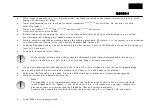
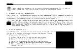
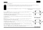
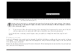
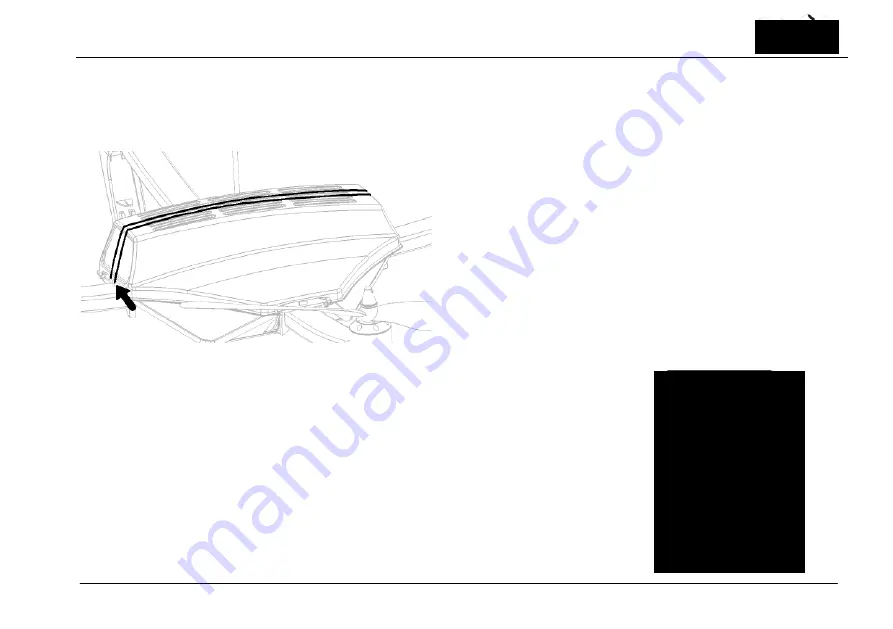
Use for the assembly of the upper cover the beliegenden rubber bands. In addition you thread an arm by the volume,
stretch this in longitudinal direction over the cover and f a s t e n i t afterwards at the hook of the Kunststofrahmens. Use
f o r safety reasons t w o volumes
mo v in g in o p p o s it e d ir e c t io ns
.
6 .
A s s e m b l y o f t h e f l i g h t d i r e c t i o n i n d i c a t o r ( a l r e a d y i n s t a l l e d )
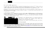
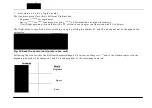
Push the folded up flight direction indicator into the guide rails in a landing leg of your
choice, until this lines up. Normally it c o n c e r n s t h e r e b y the leg w h i c h is arranged in
t h e
s t r a ig ht fl ig ht
forward.
The flight direction indicator which can be installed in a load leg facilitates i t for you to
recognize the flight direction. For the assembly you orient yourselves please at fig. 02 on
page 22. The flight direction indicator should be installed at the upp er load leg and
s i g n a l e d thus „in front ".
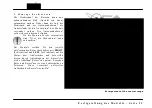
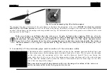
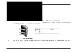
Fig. of 06 flight direction
indicators
Bild 05 Abdeckung

