Page 5
TC3 “O” V2
RC Product Designs
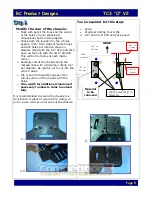
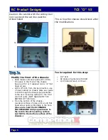
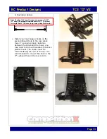
Modify the rear of the chassis:
Ø
Mark with pencil the lines and the center
of the holes on your chassis per
dimensions shown in the diagram
Ø
Prick punch the location for the 4 holes
approx. 3/16” from sides of marked lines
and drill holes per location shown in
diagram (start with the 1/8” drill, and then
open up the hole with the 3/16” drill bit).
This will be the radius at each inside
corner.
Ø
Carefully cutout the chassis along the
marked lines with a Dremmel cutting tool
per diagram. Be careful not to cut into the
corner radius.
Ø
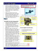
File or sand to blend the edges of the
cutout section of the chassis with the
holes.
Ø
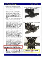
Trim width for additional clearance if
necessary to allow A-Arms to extend
fully
It is recommended to secure the chassis to a
work bench or piece of wood with a clamp, or
put in a vise while you drill and cut the chassis.
1.
1.5
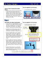
Tools required for this step:
Ø
Pencil
Ø
Dremmel Cutting Tool & File
Ø
1/8” and 3/16” drill and prick punch
2.
3.
Material
to be
removed
Drill 4 holes 3/16” in
diameter.
.093” or
2.4mm
.093” or
2.4mm
1.05” or
26.7 mm
25/64”
or 10 mm
0.25” or
6.35 mm


