TC3 “O” V2
RC Product Designs
Page 6
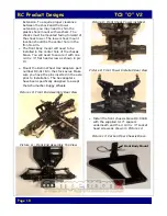
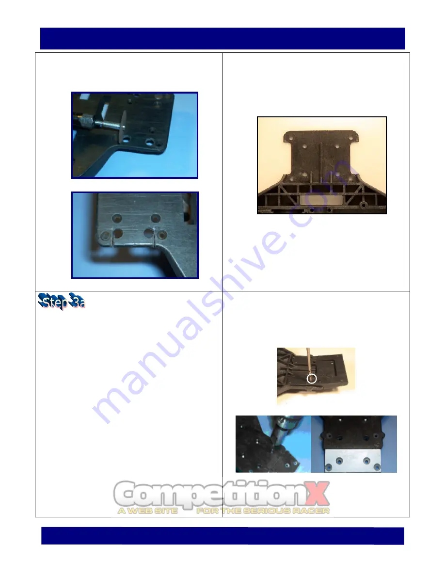
Caution: Be careful with the cutting tool
not to extend the cut-line past the
drilled holes!
4.
5.
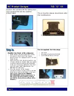
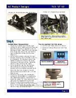
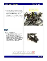
This is how the chassis should look after
the modifications.
6.
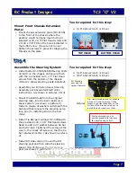
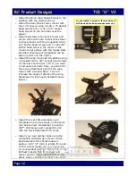
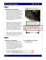
Modify the Front of the chassis:
Ø
Slide chassis extension plate (DC-015B)
into place in the front of the chassis.
Secure with 2 or 3 supplied 4-40 x ¼” Flat
Head screws.
Ø
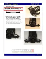
With 1/8” drill, from the top direction, use
2 holes marked on chassis plate as a guide
to drill through the chassis perpendicular
to the new mounting surface for the front
A-Arm Mounts. (NOT SQUARE TO THE
BOTTOM OF THE CAR).
Ø
From the bottom of the chassis,
countersink those 2 holes until a 4-40 Flat
head screw nests comfortably in the hole.
(Be sure to hold the 82 DEGREE
COUNTERSINK drill perpendicular to
the A-Arm Mount mounting surface
and NOT to the bottom surface of the
chassis.)
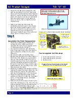
Tools required for this step:
Ø
1/8” drill
Ø
82 degree Countersink Drill Bit
Ø
1/16” Allen Wrench or Driver


