Page 7
TC3 “O” V2
RC Product Designs
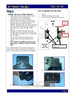
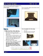
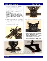
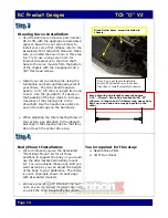
Mount Front Chassis Extension
Plate:
Ø
Mount chassis extension plate (DC-015B)
to the front of the chassis where the
gearbox would normally mount using 4
supplied 4-40 x 1/4” Flat Head screws and
2 4-40 x 3/8” FHS in the holes indicated in
the bottom view. (Be sure not to over
tighten the screws to prevent stripping the
threads on the plate.
Tools required for this step:
Ø
1/16” Allen Wrench or Driver
Assemble the Steering System:
Ø
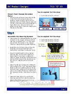
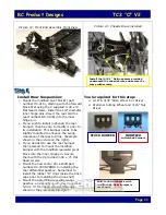
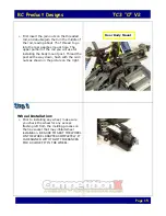
Install parts DC-005B/006B Steering Posts
LH & RH on the chassis and secure them
with the 2 provided 4-40 x ½” Flat Head
screws from the bottom of the chassis.
(Picture 1 shows steering posts installed).
Ø
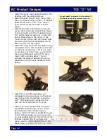
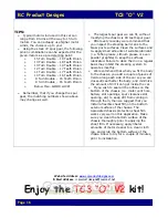
Assemble your B3 Servo Saver Steering
Assembly per Associated Electronics’
instructions.
(As shown in pictures 2 & 3)
Ø
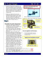
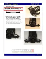
Mount the Ball Studs from the original
steering rack, into the bell crank/servo
saver system.
(As shown in picture 4).
Install a couple of washers underneath the
ball stud that connects the steering servo
link, prior to installing stud in the bell
crank
.
Ø
Install Tie Bar part number DC-008B with
the provided 4-40 x 3/8” Flat Head screws.
Need to add a #4 washer between tie bar
and bell crank. Tightened the screw all the
way in, then back off screw so that the tie
bar rotates smoothly.
(As shown in picture
4).
Ø
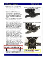
Install RH side crank arm over the RH
steering post and then slide the steering
spacer (DC-007B) over the RH steering
post
(As shown in picture 4).
Tools required for this step:
Ø
0.16” Allen Wrench or Driver
Ø
3/32” Allen Wrench or Driver
Picture1
Picture 2
RH Steering
post has the
Larger Diameter
Tip: Use a small amount of suitable
lubricant (Lithium grease, Teflon
grease or powder graphite) on the
surface of the brass posts prior to
install the bell crank over them.
We recommend you use
powder graphite to lubricate
the beveled edges first.
3/8”
1/4”
TOP VIEW
BOTTOM VIEW


