there is a tendency toward accentuation of low frequencies,
which may result in making voices sound “boomy.” In this re-
spect the use of the uni-directional microphone differs greatly
from that of the condenser microphone, with which the soloist
usually works at a distance of from 4 to 6 inches. As a point of
useful information, it may be mentioned here that the uni-di-
rectional microphone may be used as a close-talking micro-
phone by talking in the plane of the ribbon. In this position, only
the pressure-operated part of the ribbon is used.
e placement of a speaker or musical instrument off from the
center line of the microphone will in no way affect the quality
of pick-up, but will merely attenuate the direct sound pick-up,
thereby raising the ratio of reverberation to direct pick-up.
e microphone is uni-directional. Speakers, instruments or
players may be placed on the operating side of the microphone
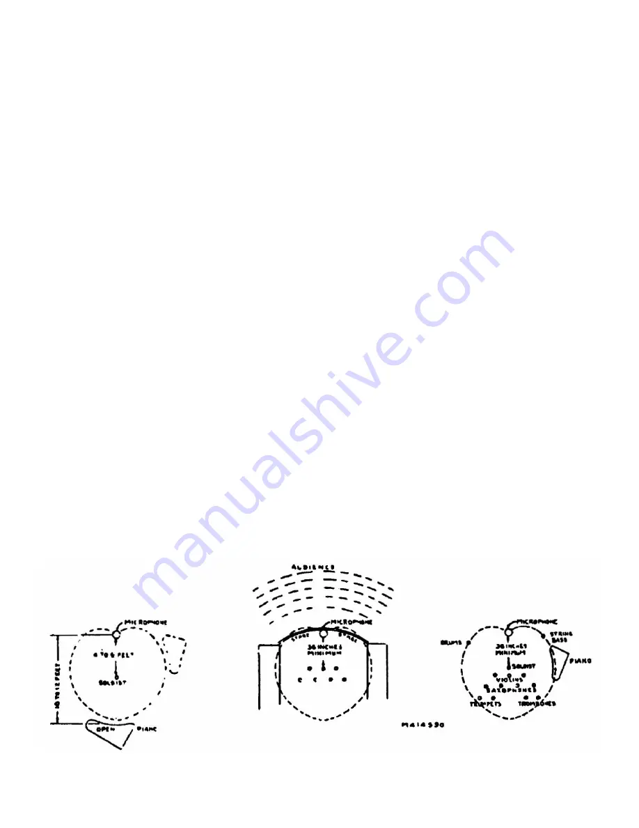
only. e diagrams (Figures 5, 6, 7, and 9) will serve as examples
which arise from the uni-directional characteristic.
For more satisfactory results, the microphone should not be
placed closer than 3 feet to any solid reflecting surface. is
statement is, of course, general and specific conditions may re-
quire otherwise.
e diagrams referred to in the subsequent paragraphs and
the discussion concerning them can only serve to indicate some
of the possible placements under particular conditions. e
final decision as to what constitutes the proper placement must
rest with someone who is competent to judge the quality of the
results as reproduced by the monitor speaker.
(b) Soloist with Piano.
—Interesting effects may be obtained
by changing the angle of the microphone with respect to the
piano, thus changing the ratio of reverberation to direct pick-
up. e distance between the soloist and the microphone
should be determined by the strength of his (or her) voice, and
the piano should be placed accordingly. e general arrange-
ment is shown in Figure 5. Under no condition should the
soloist be less than 2 feet from the microphone.
(c) Stage Plays.
—In the case of stage plays and those pick-ups
of the type that occur in the case of auditorium-type studios,
where a sizeable audience is present—and in remote pick-ups
at theatres, night clubs and the like, where audience noise is a
serious problem, the use of the uni-directional microphone
possesses a distinct advantage. By placing the microphone with
its dead side toward the audience and close to the footlights, or
in an equivalent position, the 20-dB discrimination will provide
the desired attenuation of audience noise, while the broad pick-
up angle—useful through nearly 150 degrees—will afford pick-
up of the whole stage, or that part of the studio where the artists
are located. See Figure 6.
(d) Dance Orchestra.
—e set-up for dance orchestra is sim-
ilar to that just outlined for stage plays, the dead side of the uni-
directional microphone being toward the dance floor. e
diagram (Figure 7) is self-explanatory, the only precaution nec-
essary being to keep the soloist at least 2 feet, and preferably 3
feet, from the microphone.
In locating the microphone with respect to an orchestra, care
should be taken to avoid reflected pick-up from hard-surfaced
floors. Such reflections can be avoided by the use of carpets or
similar material on the floor.
(e) Large Orchestra.
—An arrangement for a large symphony
orchestra is shown in Figure 9. It is to be noted that the wide
angle of coverage (150 degrees) of the uni-directional micro-
phone will permit a satisfactory pick-up in many cases, such as
that shown, with but one microphone. It must be borne in
mind, however, that the physical proportions and acoustic
properties of the studio have a direct bearing on the arrange-
ment of the orchestra and placement of the microphone. Where
space considerations do not govern, changes from the arrange-
ment shown should not necessarily be very extensive in order
to give excellent results under the usual acoustic conditions.
(f ) Public Address.
—For public address use, the microphone
can usually be placed near the loudspeakers (within 3 or 4 feet).
It is important to see that the dead side of the microphone is to-
ward the loudspeaker system—more specifically, the micro-
phone should not be placed in front or directly behind the
loudspeakers to prevent acoustic feedback. If the speaker must
have latitude of movement on the stage, it may be necessary to
have a microphone installed at each side to obtain satisfactory
pick-up.
(g) Sound Reenforcing.
—Microphones used for this purpose
must generally be concealed and may be successfully operated
in the wings, flys, etc., or at the front of the stage, where some
simple method may be devised for their concealment. Such a
system usually requires the use of a number of microphones
Figure 5—Soloist with Piano
Figure 6—Plays
Figure 7—Dance Orchestra
VARIOUS MICROPHONE ARRANGEMENTS
Summary of Contents for 77-A
Page 7: ......


