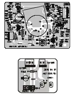
SERVICE , MANUAL
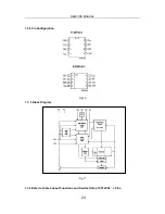
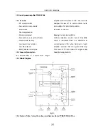
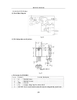
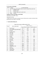
b. Pin function for STR-F6654
Pin No. Symbol
Function Description
1
OCP/FB Over-current protection detection signal/ voltage-limiting signal input
2
S
MOSFET source
3
D
MOSFET drain
4
V
IN
Supply voltage input for control circuit
5
GND
Ground
(4)Difference between STR-G5653 and STR-F6654
a.Different size: STR- F6654 is larger
b.Different pin functions
c.Different electric characteristics: Larger power output, switching current, avalanche-rated and internal
allowable power consumption for STR-F6654
2.
Service Data of Key ICs
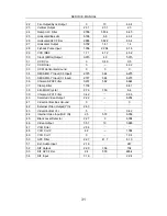
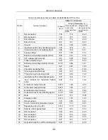
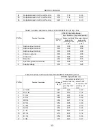
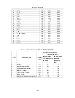
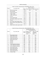
Table 2 Service Data of LA76818A (N101)’s Pins
GDM8145 Multimeter
Pin No.
Function Description
Voltage(V) Positive Resistance(k ) Negative Resistance(k )
1
Audio Output
2.2
6.82
7.6
2
FM output/Selected Audio Output
2.41
6.59
486.6
3
PIF AGC
1.98
6.99
512.7
4
RF AGC Output
3.73
26.4
5
PIF Input1
2.84
6.71
29
6
PIF Input2
2.84
6.71
7
IF Ground
0
0
0
8
IF Vcc
5
0.41
0.38
9
FM Filter
2.22
7.06
0.76
10
AFT Output
4.75
5.28
11
Bus Data
4.8
14.48
380
12
Bus Clock
4.8
5.316
360
13
ABL
3.24
7.036
172
14
Red Input
0
7.04
17.5
15
Green Input
0.022
7.02
60.5
16
Blue Input
0.022
7.03
6.02
17
Fast Blanking Input
0.015
3.24
3.2
18
RGB Vcc
8.234
0.46
0.45
19
Red Output
2.8
5.33
6.05
20
Green Output
2.96
5.34
6.07
21
Blue Output
2.8
5.33
6.05
30
Summary of Contents for MCR51R410
Page 15: ...14 STRUCTURE AND CHASSIS FUNCTION DESCRIPTION 1 Structure Block Diagram ...
Page 16: ...15 2 Block Diagram for Supply Voltage System ...
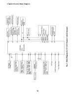
Page 17: ...16 3 System Control Block Diagram ...
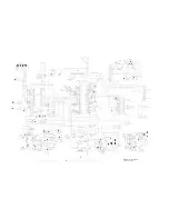
Page 38: ......
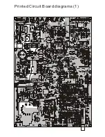
Page 39: ...Printed Circuit Board diagrams 1 ...
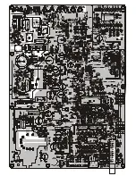
Page 40: ......
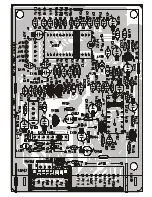
Page 41: ......

