justed for a further minimum
value, which will not now be located at one of
the extreme positions.
(c) After making any potentiometer adjustment, further reduction of hum may be attempted by
reversing the input plug.
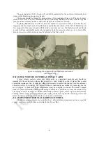
When adjusting the potentiometer at the extreme right with a metallic screw driver a flash will occur
from the screw driver to any part of the frame that the screw driver may touch. This is normal and does no
harm. If it is desired to avoid this condition, an insulated shaft screw driver or a metallic screw driver
wrapped with insulating tape should be used.
(.d) If these various adjustments suppress the A. C. hum correctly, but after a short time the hum
reappears it is a good indication that some of the
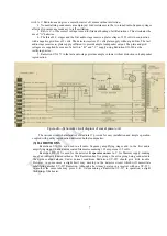
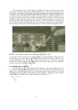
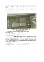
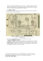
Figure
15
—
Wiring diagram of sub-chassis assembly showing color scheme
and connections with relative location of parts.
Radiotrons are making poor socket contacts, thus destroying the electrical center of the filament
potentiometers. These prongs should be cleaned as described in Part I, Section 9.
If at any time the Radiola is changed from one electrical outlet to another outlet or Radiotrons are
interchanged or replaced with others it may be necessary to readjust one or more of the potentiometers.
(20) LINE CONTROL SWITCH
The line switch should be kept at the position of least brilliancy for the pilot lamp, provided there is
no change in signal strength. This will materially increase the life of all the Radiotrons used in Radiola
17 and in many
18

