(12) REPLACING EITHER POWER TRANSFORMER OR FILTER
REACTOR
The power transformer and the filter reactor are each encased in a metal container. Either unit
may be replaced in the following manner:
1. Remove S. P. U. from cabinet as described in Part II, Section 11.
2. Unsolder the leads of the unit being replaced and tag connection points.
3. Bend -up tabs that hold unit to base. It may be necessary to remove the resistance unit in order
to bend all the tabs. The particular assembly being replaced may now be removed and the new
assembly placed in the position occupied by the old one.
4. The tabs on the new assembly should be bent so
as
to properly fasten the unit to the S. P. TJ.
base.
5. Connect all leads from the assembly to the points of connection as indicated by tags
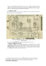
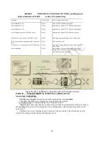
previously attached. These connections are shown in Figure 16 which should be followed exactly
when any S. P. U. part is replaced.
6. Connect cable from receiver assembly to terminal strip of Socket Power Unit. If found 0. K.
return unit to cabinet in the reverse order.
(13) REPLACING TERMINAL STRIP
Should a terminal strip on the Socket Power Unit require replacement the following procedure
should be used:
1. Remove S. P. U. from cabinet as described in Part II, Section 11.
2. Unsolder and tag all leads soldered to terminal strip.
3. Release two screws holding strip to S. P. U. base.
4. The strip may now be removed and replaced by a new one.
5. Fasten new strip in position occupied by old strip by means of two machine screws, lock
washers and nuts previously removed.
6. Solder all leads to terminal strip as indicated on tags attached. The color scheme and correct
connections are shown in Figure 16.
7. Connect cable from receiver assembly and test Radiola. If found operating properly return S. P.
U. to cabinet in the reverse order.
(14) REPLACING MISCELLANEOUS PARTS IN S. P. U.
The potentiometers, line switch, UX-280 socket and resistance unit in Radiola 17 may become
defective and require replacement. They are all attached to the base by means of machine screws and
nuts and replacement is very simple. The following general outline will apply to all of these units:
1. Remove S. P. U. from cabinet as described in Part II, Section 11.
2. Unsolder leads from defective unit and tag each lead.
3. Remove defective unit from base and replace with new unit.
4. Solder leads to new unit as indicated on tags or see Figure 16.
5. Connect cable to S. P. U. from receiver assembly. Test and if found O. K. return S. P. U. to
cabinet in reverse order of that used to remove it.
31

