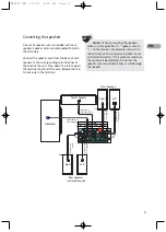
Connecting the antennas
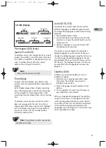
The AM and FM antennas connect to the AM and
FM terminals on the system’s back panel. They
must be hooked up in order to receive clear
reception.
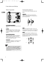
AM Loop Antenna and FM Indoor
Antenna
1. Uncoil the AM Antenna wire.
2. Press down on the Antennas tab to open the
terminal.
3. Make sure the white wire on the AM loop
antenna is inserted into the AM loop terminal
and the other wire is inserted into the ground
loop terminal.
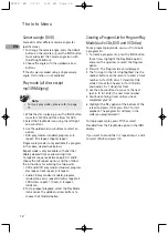
Connecting to audiovisual equipment
The jacks on the back of your receiver (shown
above) and the cables shown below are used to
connect to other components.
The video jacks are OUT jacks, which need to be
connected to IN jacks on the TV or monitor
you’re connecting to (so the video content goes
from the receiver to the screen). The audio jacks
are IN jacks, which need to be connected to OUT
jacks on the component you are connecting to, so
the sound from the component comes into the
receiver (and out through the speakers).
Video cables
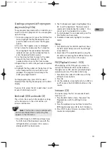
Composite video cable
(included)
The basic Video jack (color-
coded yellow) is also referred
to as composite video.
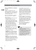
Component video cables (Pr,
Pb, Y) (not included)
The Y, Pb, Pr jacks provide
optimum picture quality by
separating the video signal into
three parts. To ensure
maximum picture quality, use three video-grade
cables for the connection. You can also buy
bundled component video cables that are color-
coded to match the Y, Pb, Pr inputs (green, blue
and red).
Audio cables (not included)
AUDIO IN L (left) and AUDIO
IN R (right)
These jacks and cables are
often color-coded (red=right
audio, white=left audio).
EN
2
Connections and Setup
FM 75
Ω
Summary of Contents for RTD217 - DVD/CD Home Theater System
Page 1: ...RTD217 ...


